Cameron Walker made a poetic search during his graduation while constantly building on his models. These pictures show how he started, please look at the presentation on the repository and see how he ended.
Cameron Walker made a poetic search during his graduation while constantly building on his models. These pictures show how he started, please look at the presentation on the repository and see how he ended.
The following text has been written by Aiden Conway. Besides the description of the project, Aiden explains how to use acrylic one in an architectural model.
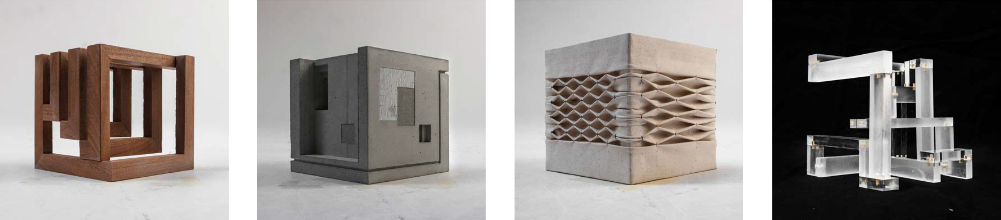
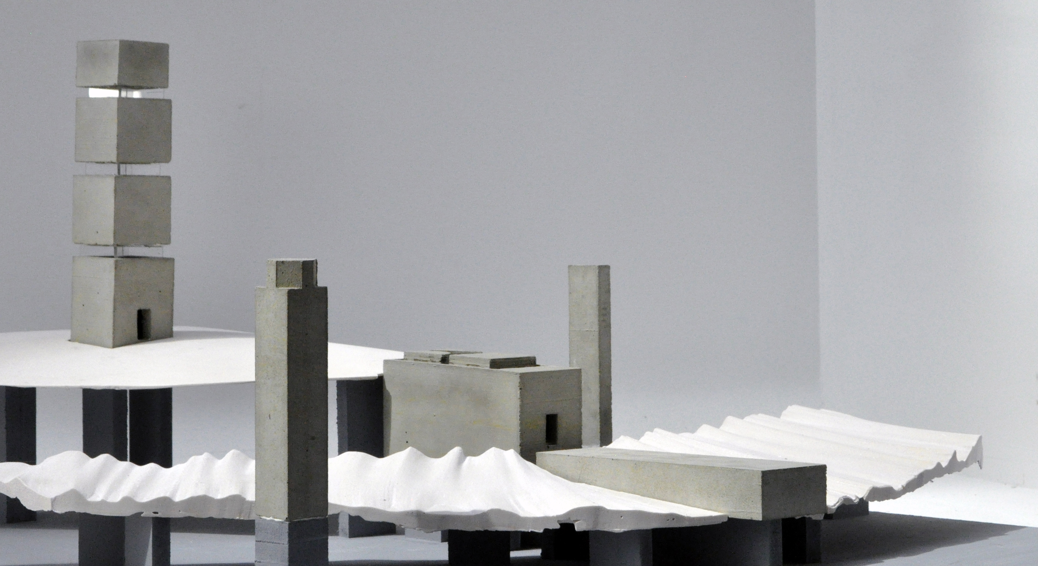
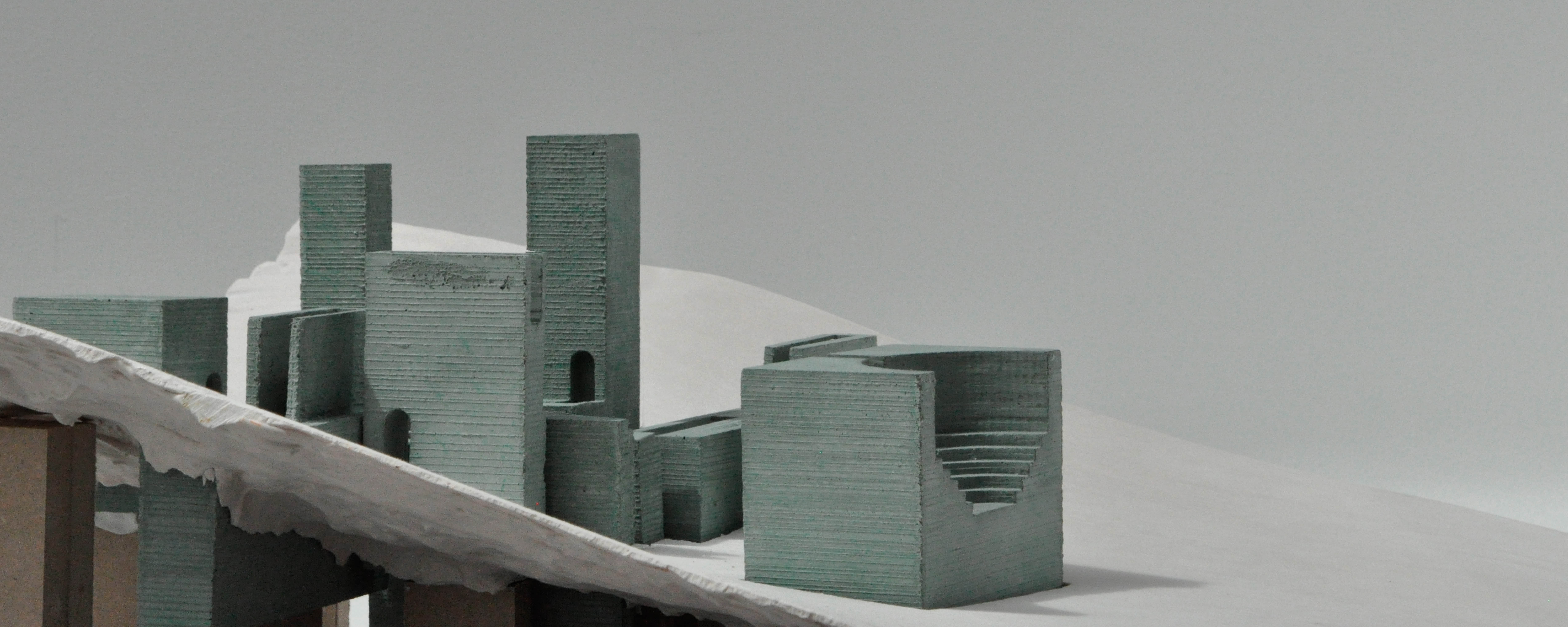
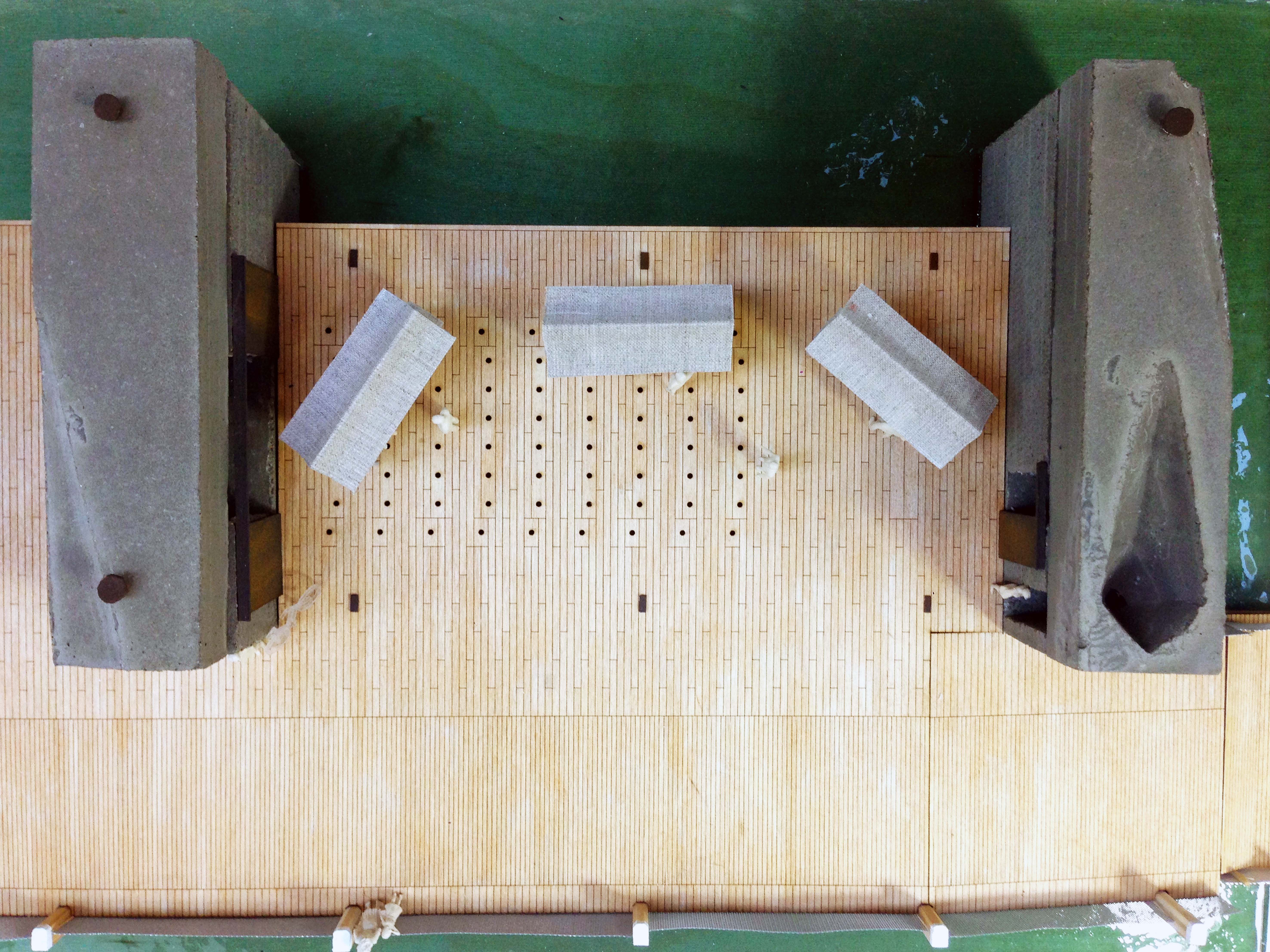
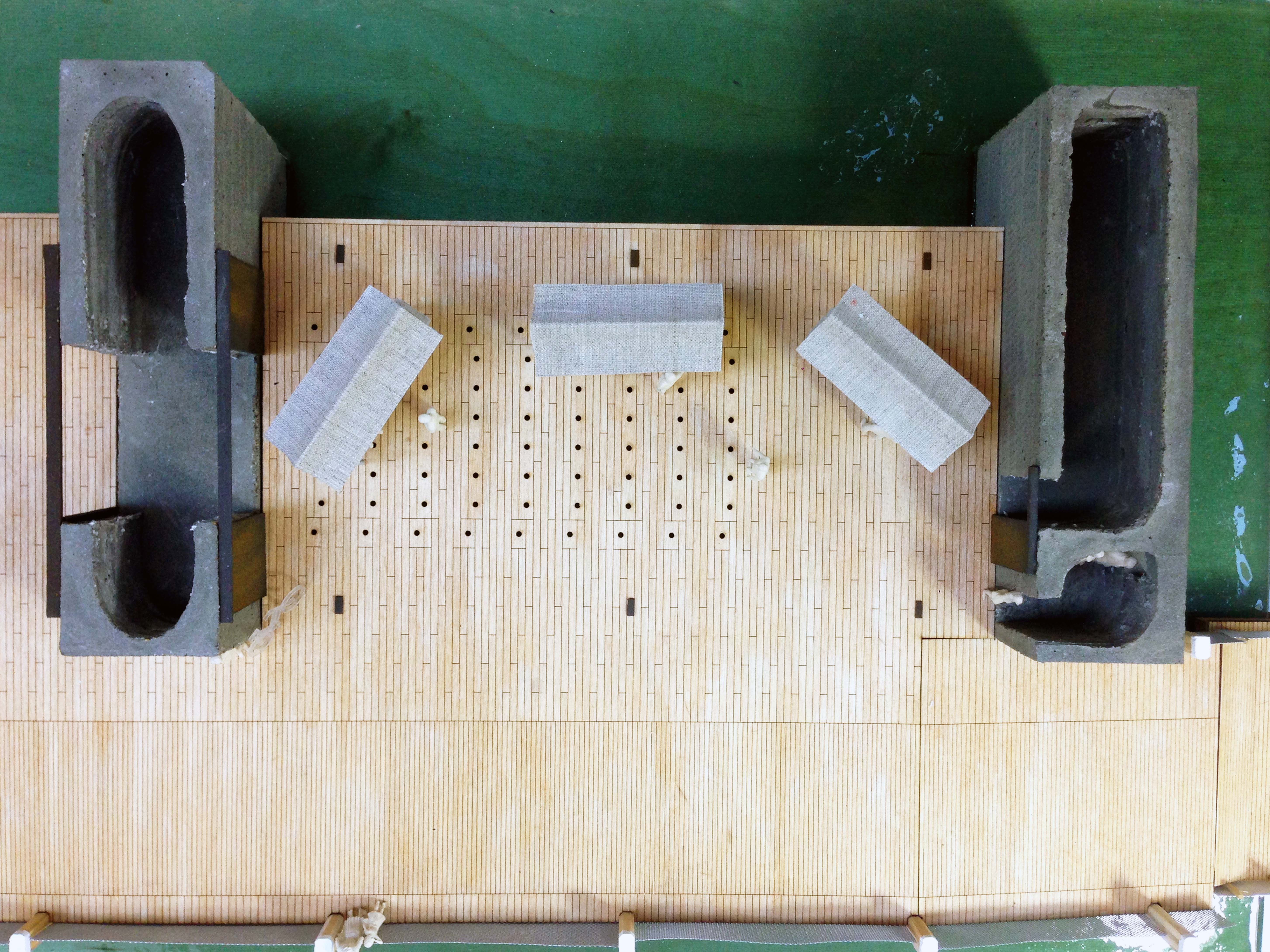
The project was aimed at discovering an approach to work in the isolated landscapes of Mayo in the West of Ireland. To do this the nature and the man made were put at odds to one another creating a conflict which would hopefully provide a method of resolving the two. This resulted in a series interventions that appear at first as a haphazard collection of volumes in the landscape, but are in fact a direct reaction to it. Each intervention creates a moment of detachment during which and an urban moment is constructed and the landscape denied, before the landscape is then reintroduced via the core function of the intervention. These forms were derived both from the study of the city and its formal components and as a reaction to the landscape in order to obscure it, reductions of both.
In any case when it came to modelling each one, the interventions was heavy and massive and wanted to contrast that by representing the landscape in a soft and light manner, as somewhat of a thin datum.
Each site and its greater context was illustrated accurately at a scale of 1:25000 in machine milled mahogany models. Because of this I thought the 1:100 models could be more expressive.
Materials Required:
-Acrylic one Mix (consisting of the mineral powder and acrylic resin)
-Flexible Sheet of Fibre reinforcing
-3mm white Foam board
-30mm Foam board
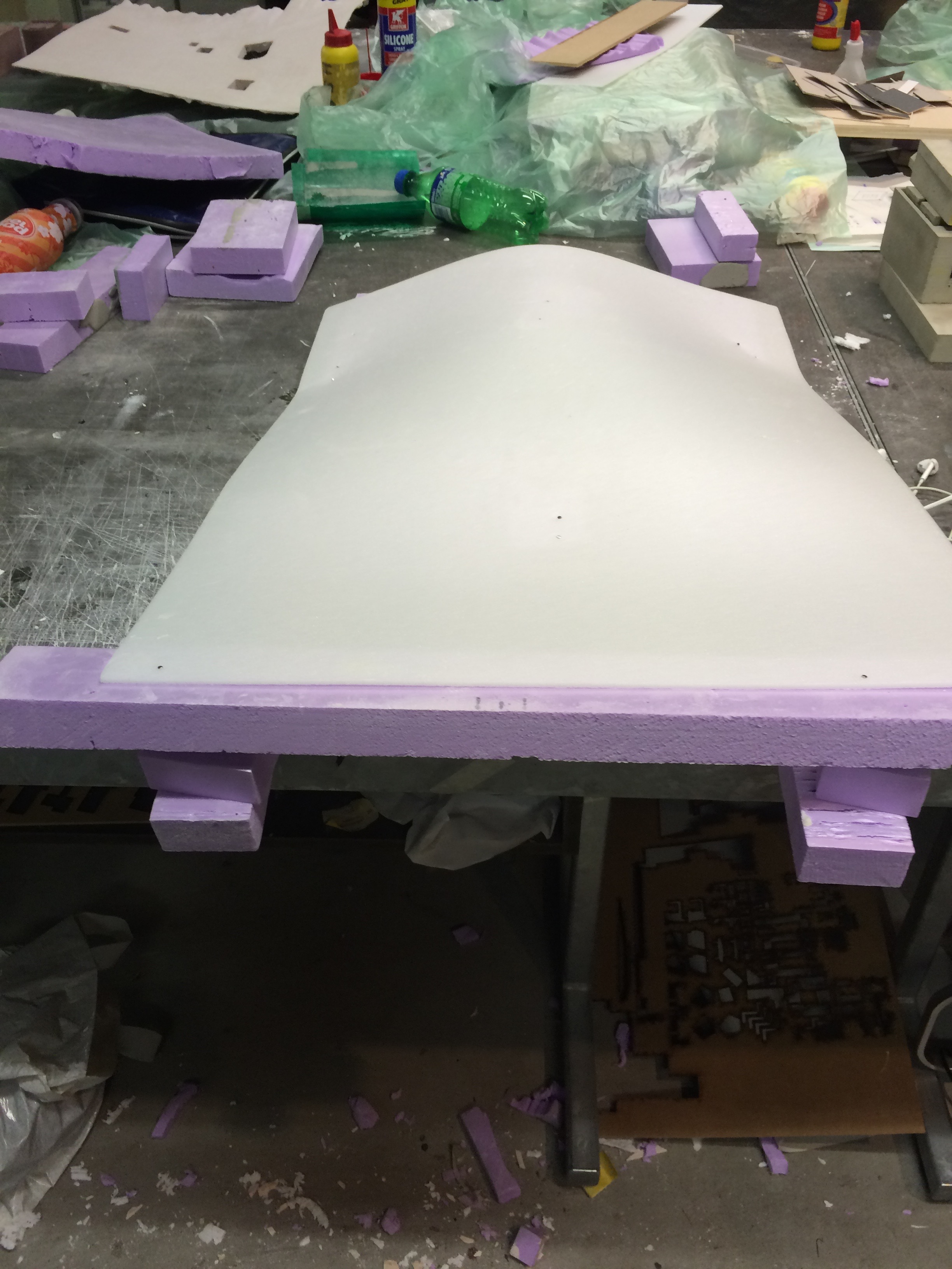
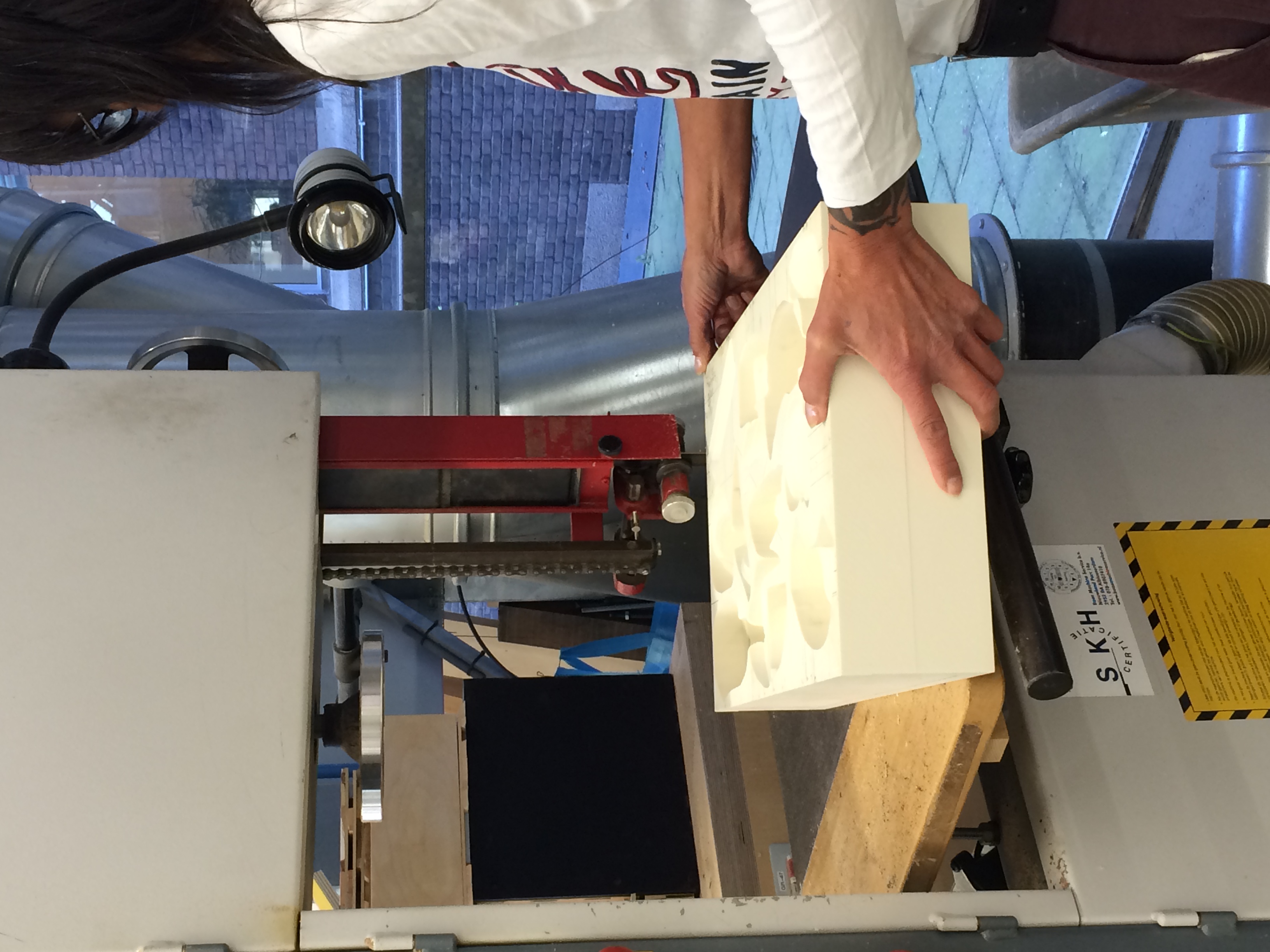
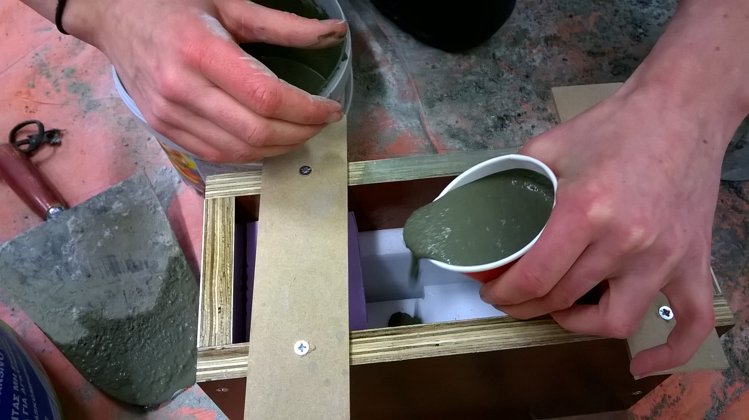
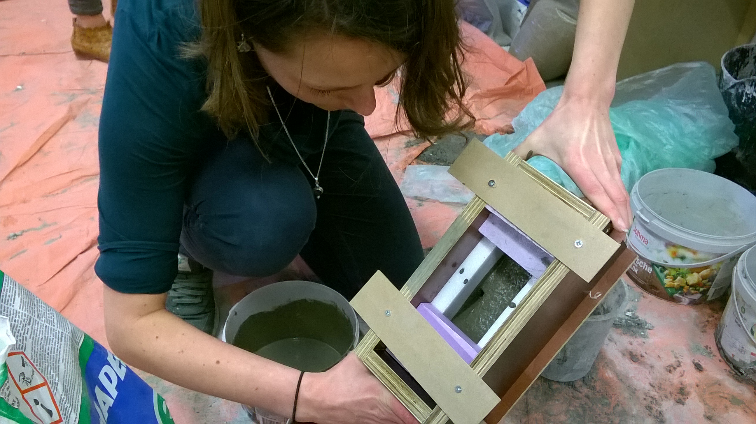
The material Acrylic One was chosen to create this thin layer. It has visual properties similar to that of plaster but is much more durable and also workable after it has dried. The mould for each site was created via bending thing layers of foam and fixing them in the desired position. The openings into which the intervening volumes (cast in coloured concrete) were to be placed, were created by foam blocks. The entire formwork is then sprayed with an even coat of silicon spray to aid the casts removal from the formwork.
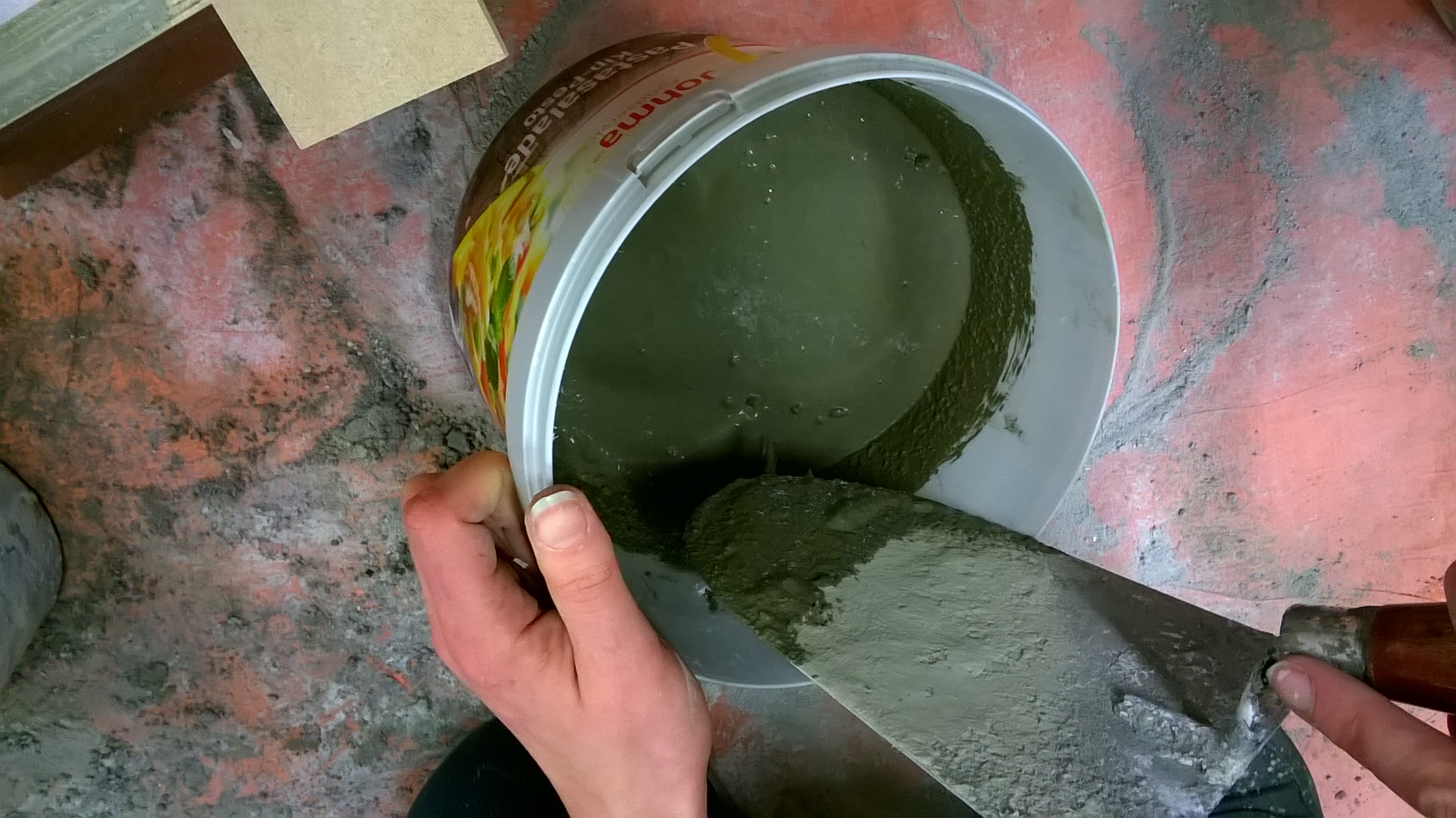
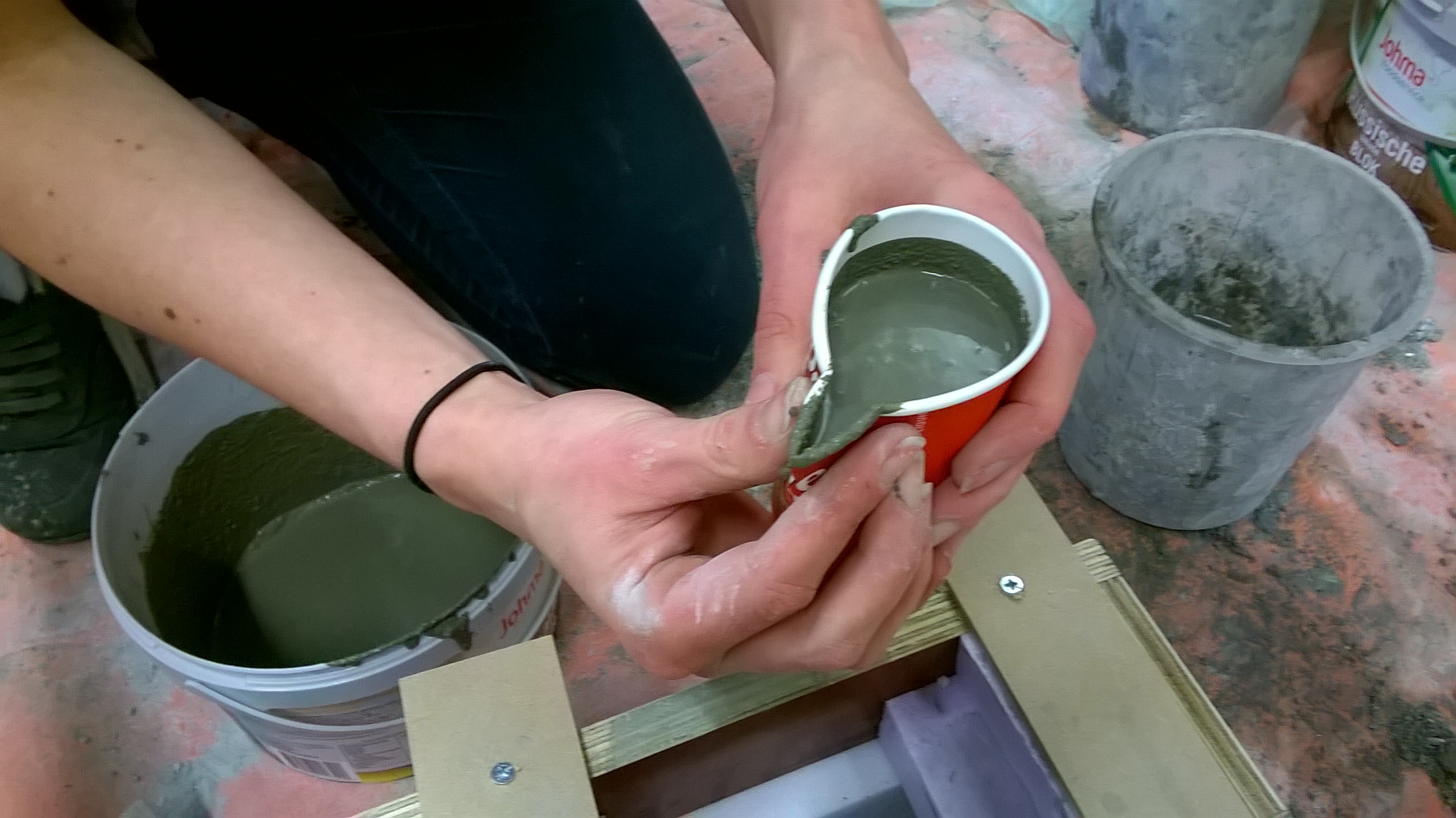
The Acrylic one which is a two-component material and consists of a mineral powder and a water based acrylic resin was then mixed at a ratio of two parts powder one part resin and applied to the surface of the foam formwork. It sets quickly and so needs to be applied rather rapidly. Its best to create enough of a mix to coat the surface in one pour so as to limit the possibility of two pours where the wet and dry don’t always bond correctly and can lead to discolouration. I chose to apply the mix with a spoon so as to use the underside of the spoon to spread it across the formwork.
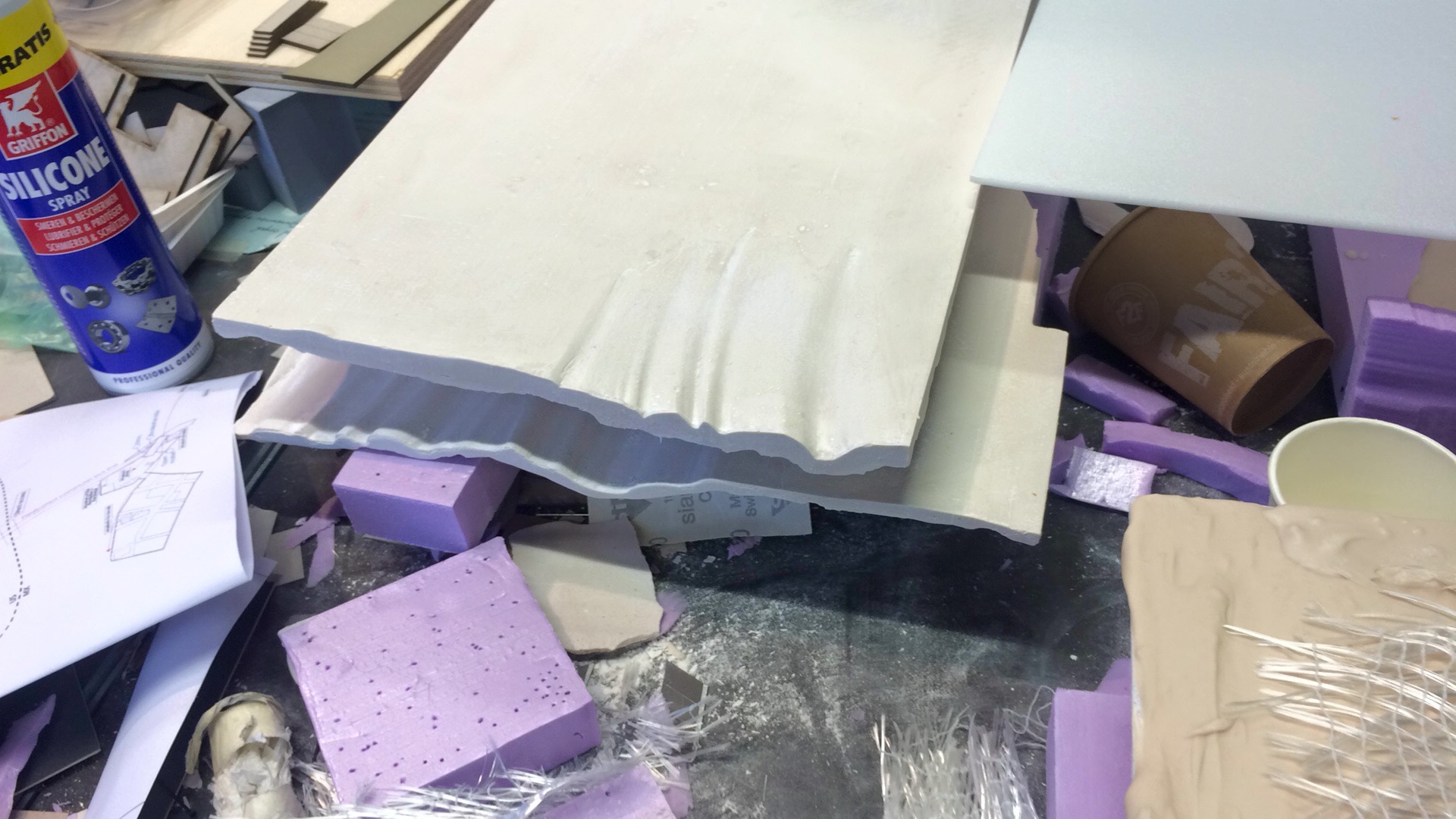
Once the initial layer is applied evenly and at a minimum thickness of 3/4mm and before its is fully dried the layer of fibre reinforcing is applied( pre-cut and trimmed to fit the formwork but also to remain at distance of 25-30mm form the desired edge of the form work so as to avoid loose and exposed threads). This should be flat to the surface and pushed gently into the still wet mix. After this the second mix should be applied. While it is preferable to pour the second mix while the first has yet to dry it is not completely necessary. The mix is then left to fully dry for at least 18 hours.
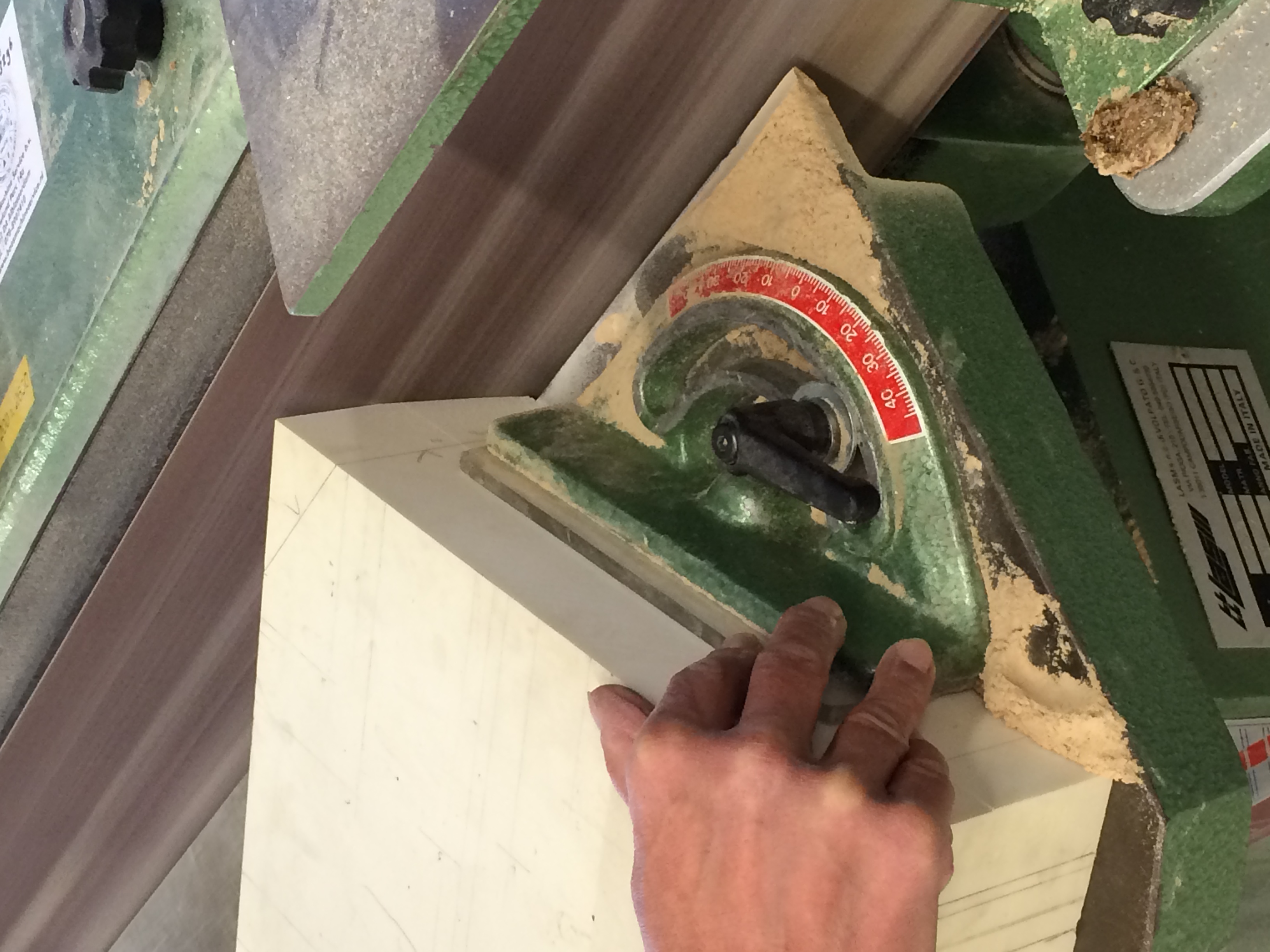
The foam formwork was removed. At some points had bonded with the acrylic was removed with the back of a knife or an upturned chisel, to scrape away the foam but also to take a thin layer of the surface with it if needed. once the form work was removed the remaining foam was sanded to the desired smooth finish. The cloth like undulations at the edges was created by cutting the curves on the wire foam cutter -passing it through vertically- this was then glued to the formwork. The best results were achieved when the joints between the formwork and the curved blocks were as smooth as possible, but if not the workability of the acrylic one allows these joints to be smoothed out afterwards.
While I only had limited time to experiment with the material I think it has many potential applications and its limitations can be pushed much further than i had managed. I’d highly recommend it not only for its aesthetic values but also its workability after being poured, by which i mean the potential to alter its finish and also carve or work the surface.
The following text has been written by Max Nibbrig to explain his graduation project. Please click on the photos and take a good look. Max learned about the craft of bronze casting, but already knew about photography. And that’s an understatement.
Foundry pt.1
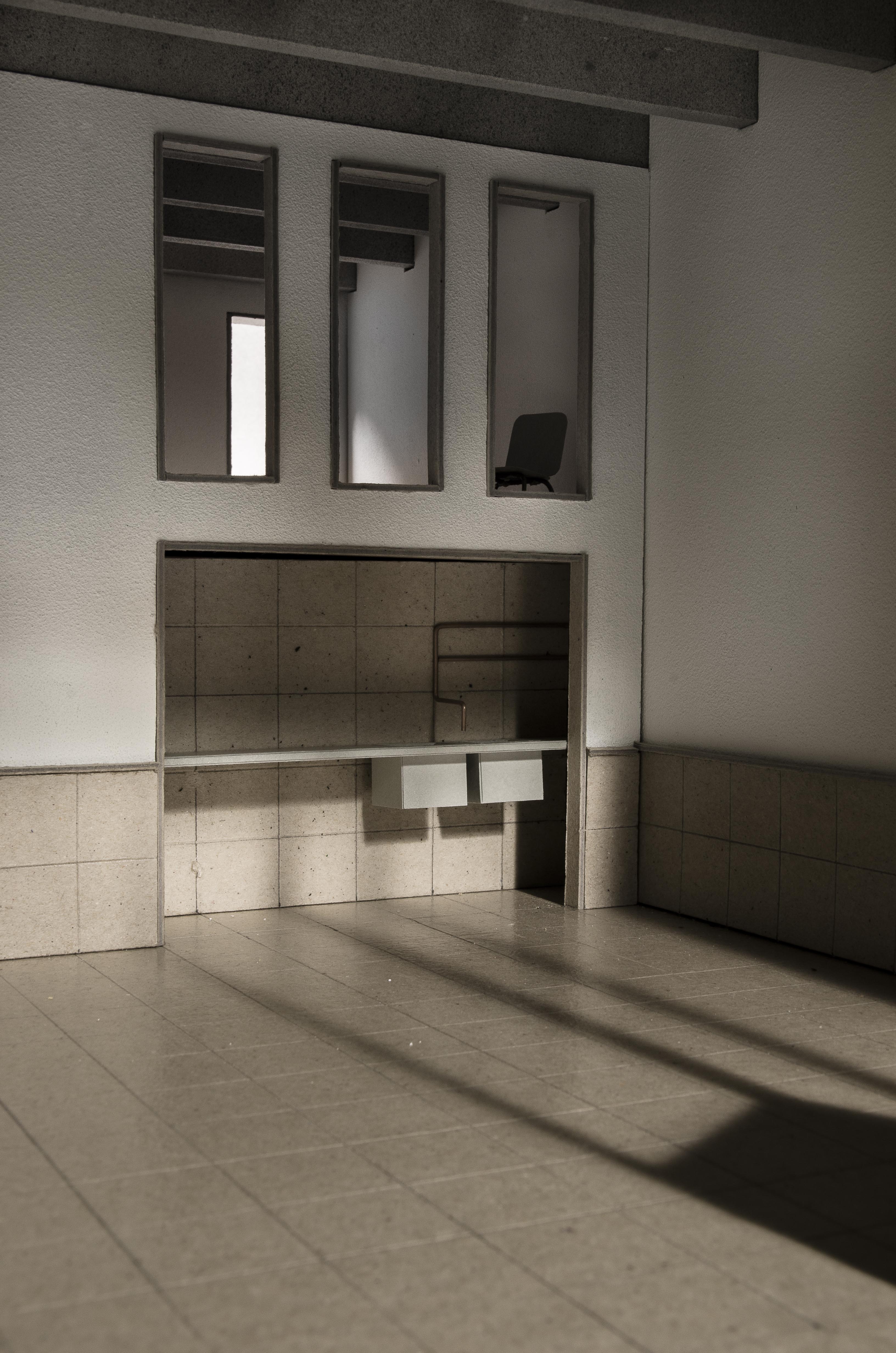
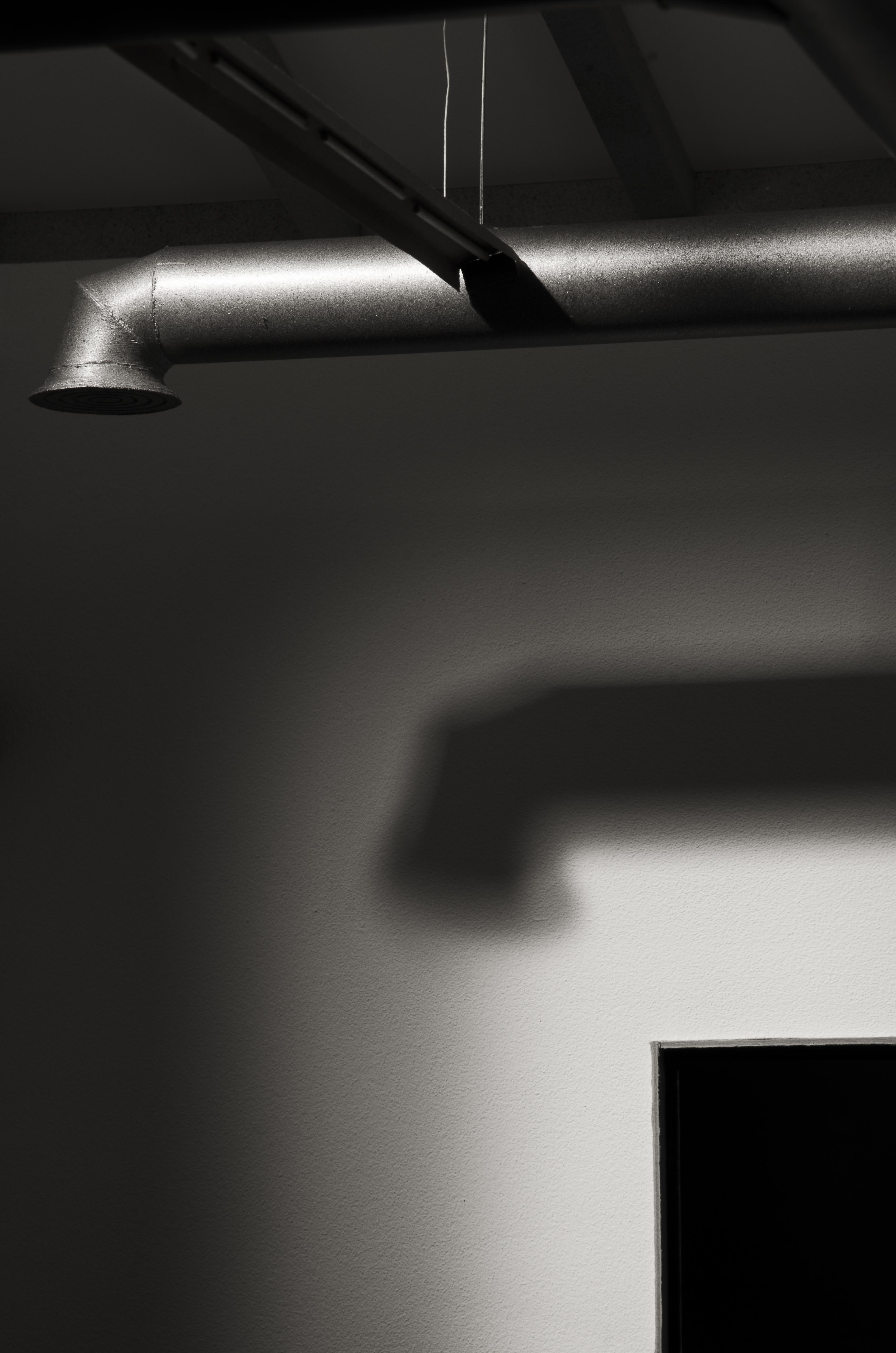
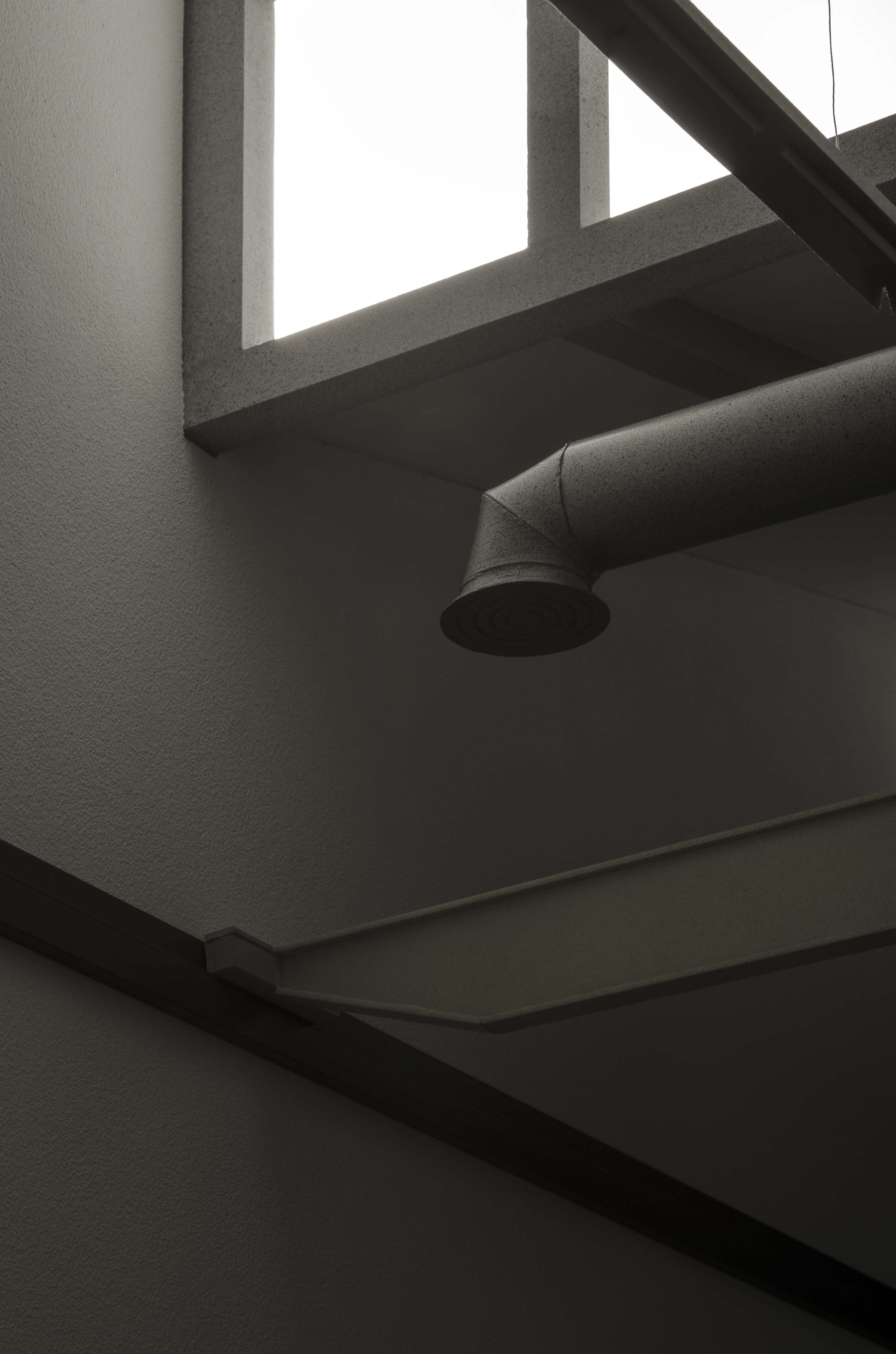
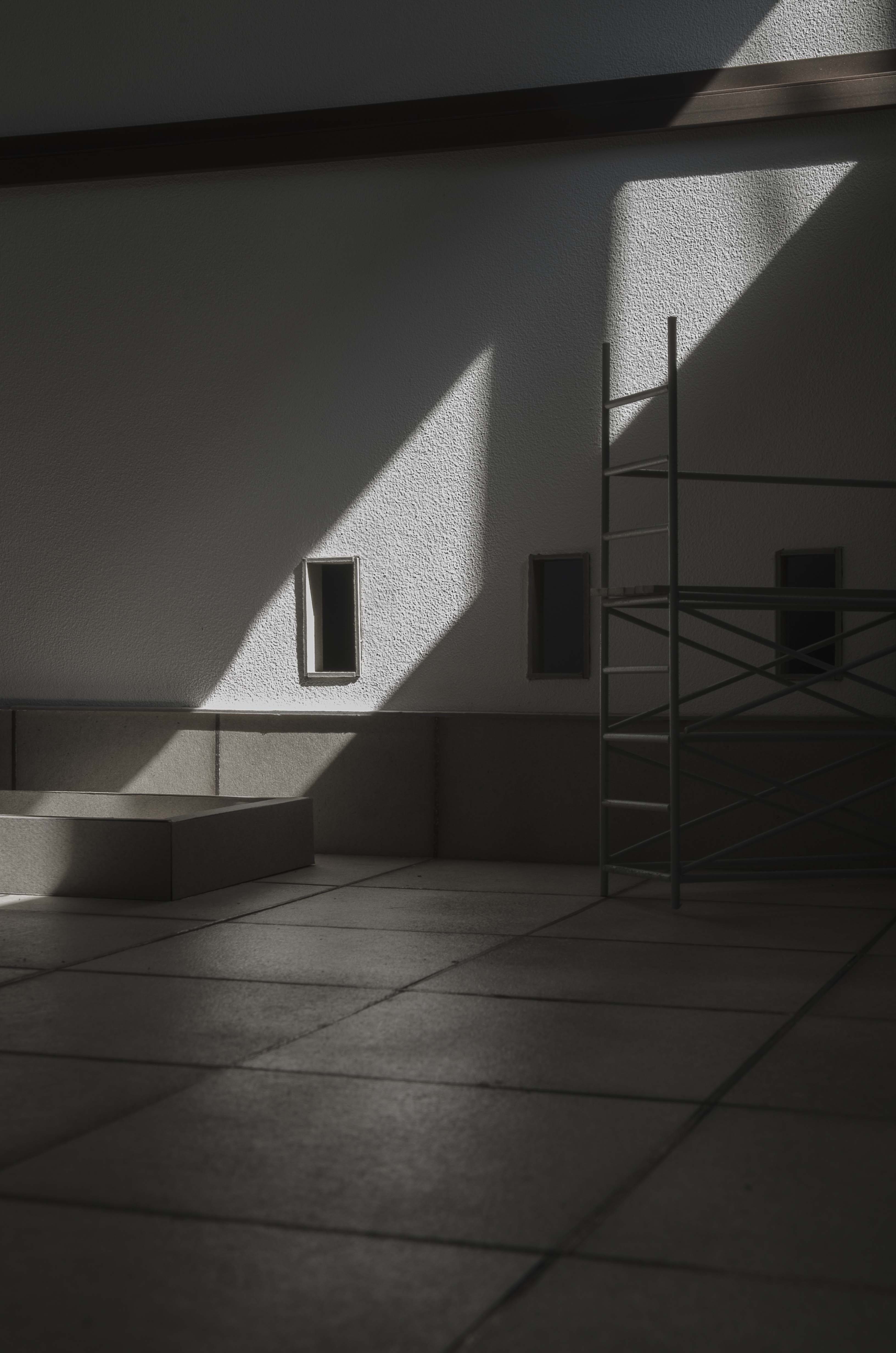
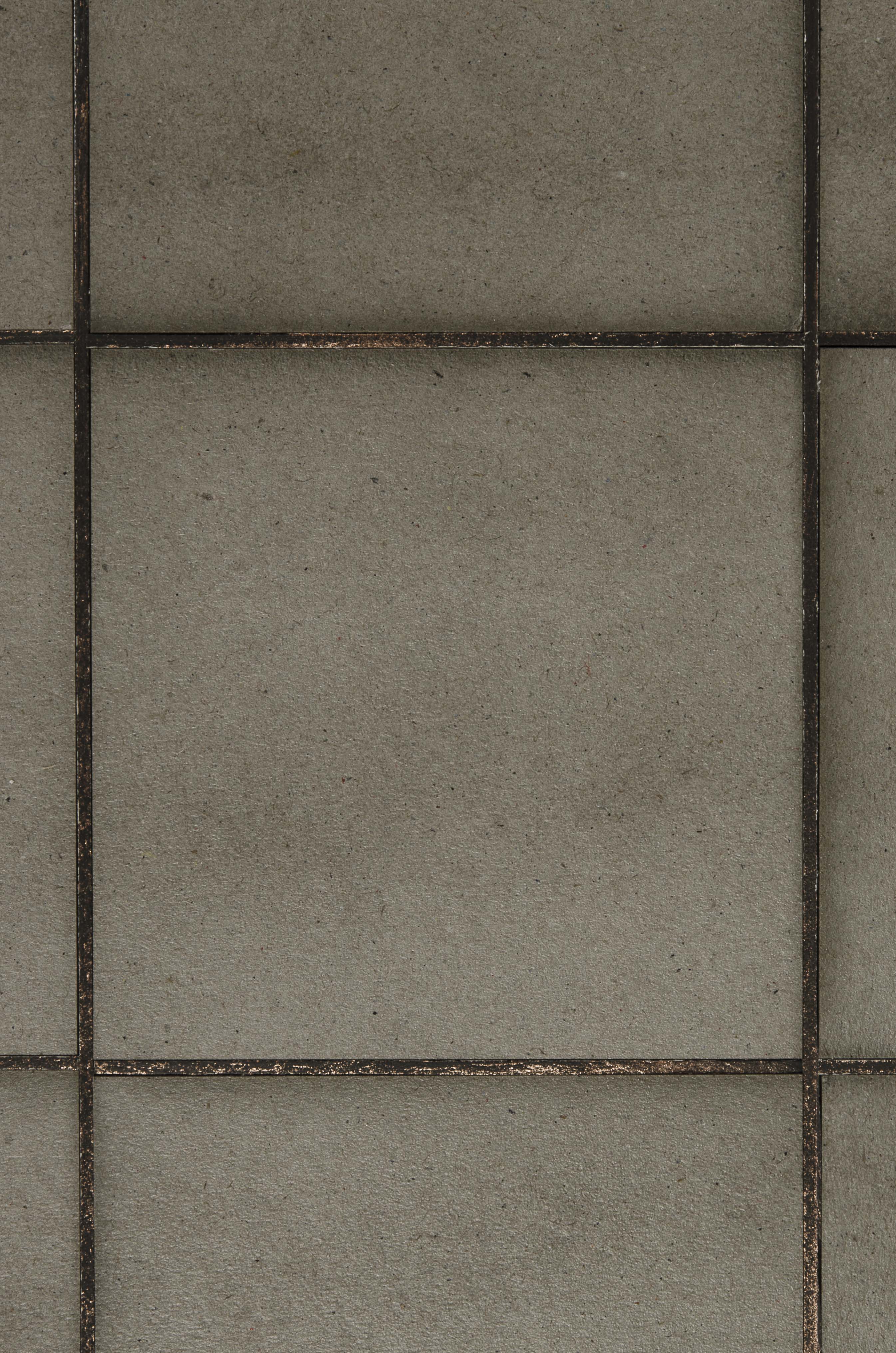
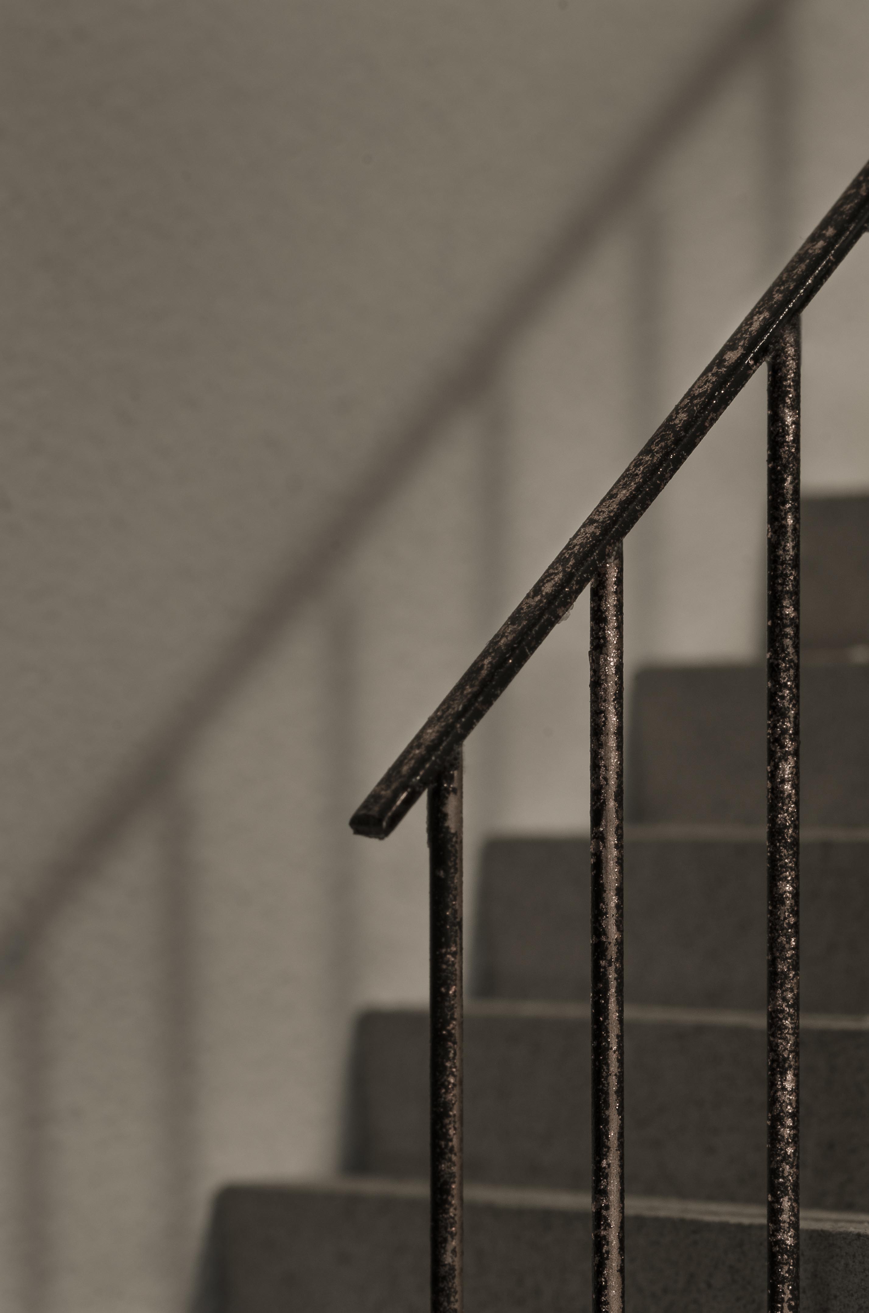
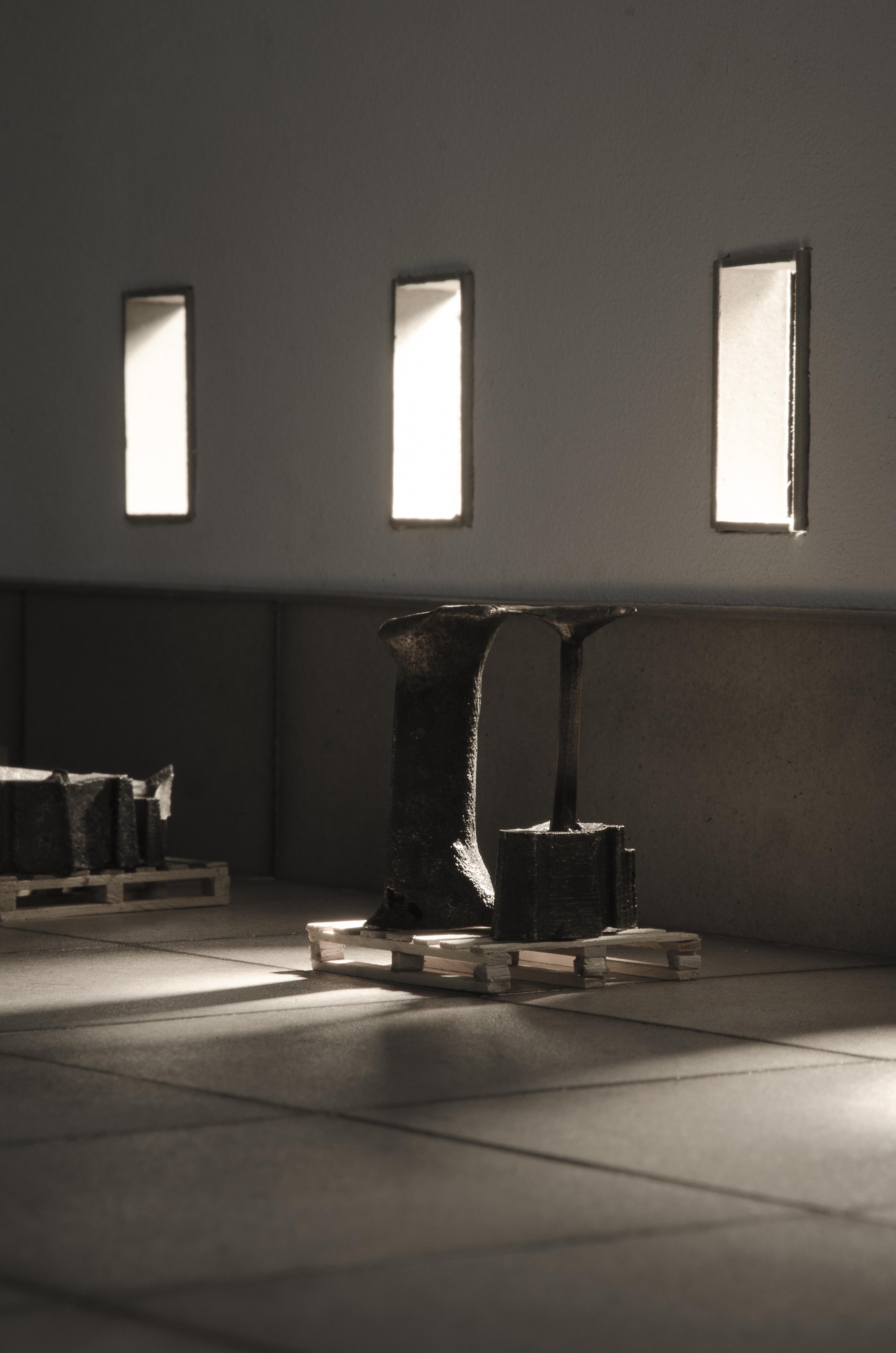
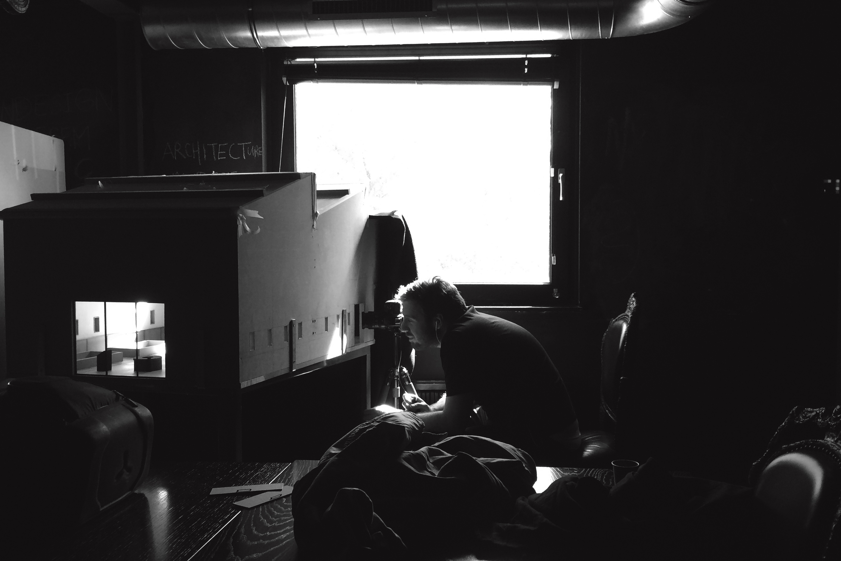
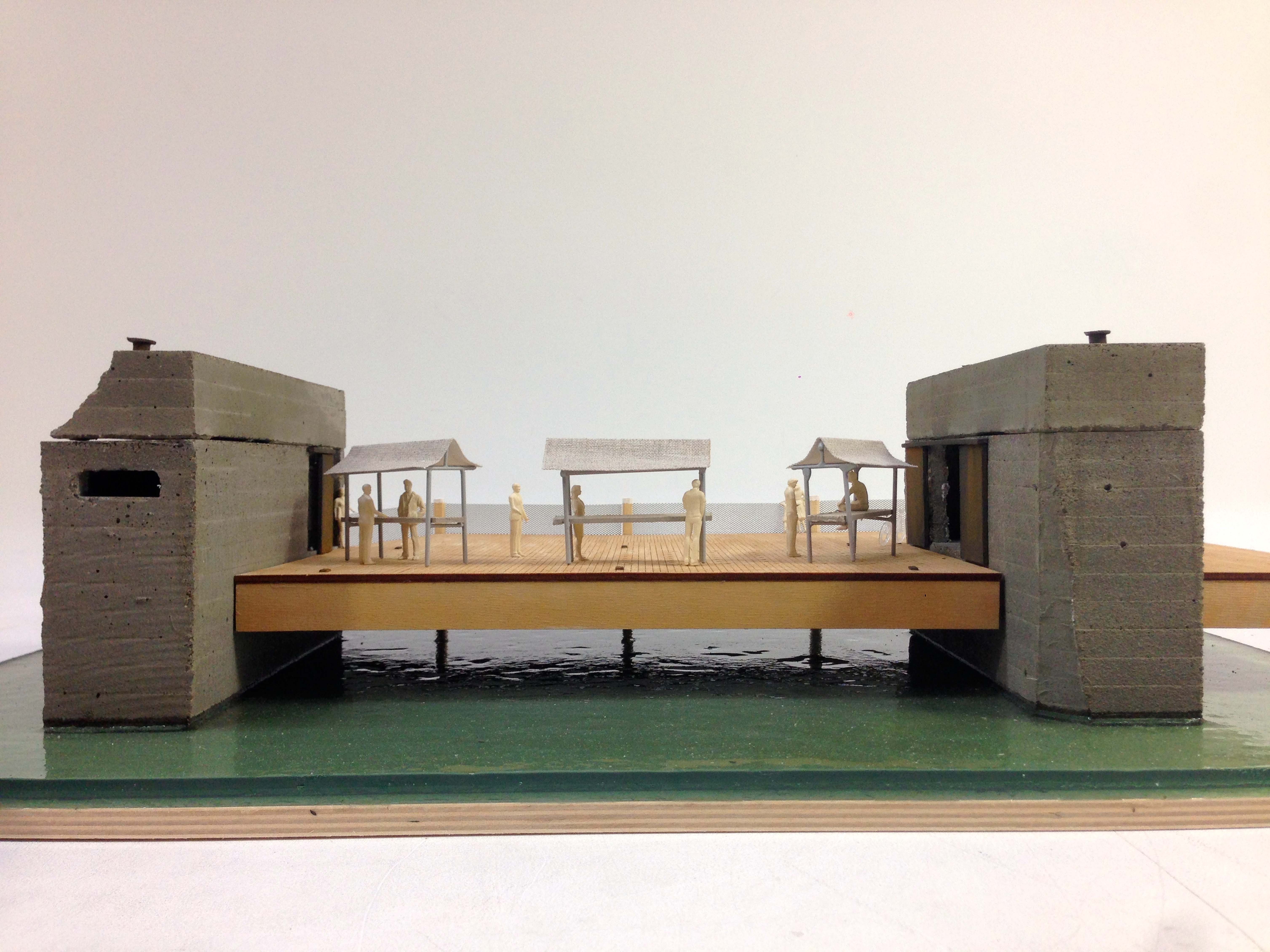
For my graduation project I designed a bronze foundry for the city of Amsterdam. The project aims at bringing back craft in to the city again by introducing a new place of work. Foundry pt.1 uses photography as a tool to explain architectural design. The images are pictures of 1:20 architectural scale models. These pictures explore spatial quality in relationship to light, atmosphere, material and use. The photo series consist out of 11 pictures divided in to four themes; Foundry, Foundry Ceiling, Artist in Residence and Material and Detail. Moments within these four themes are carefully framed to show the potential of the space and the design.
The design consists out of two buildings. The big hall is a foundry for the casting of bronze and brass. On the central axis of the building the furnace is located where metals are melted. To the left and right there are casting pits where moulds can be placed to cast metal. Along the vertical axis of the building all the technical necessities as lighting, ventilation and movement are arranged.
The smaller space is an artist in residence building where artist can work in close cooperation with the foundry. He has his atelier on the ground floor and his living space on the first floor, making it possible to look down on the work whilst not working.
Both spaces deal with a floor that changes in to a plinth when the floor meets the wall. The plinth and floor work together to define a work area where things can be created.


Foundry pt.2
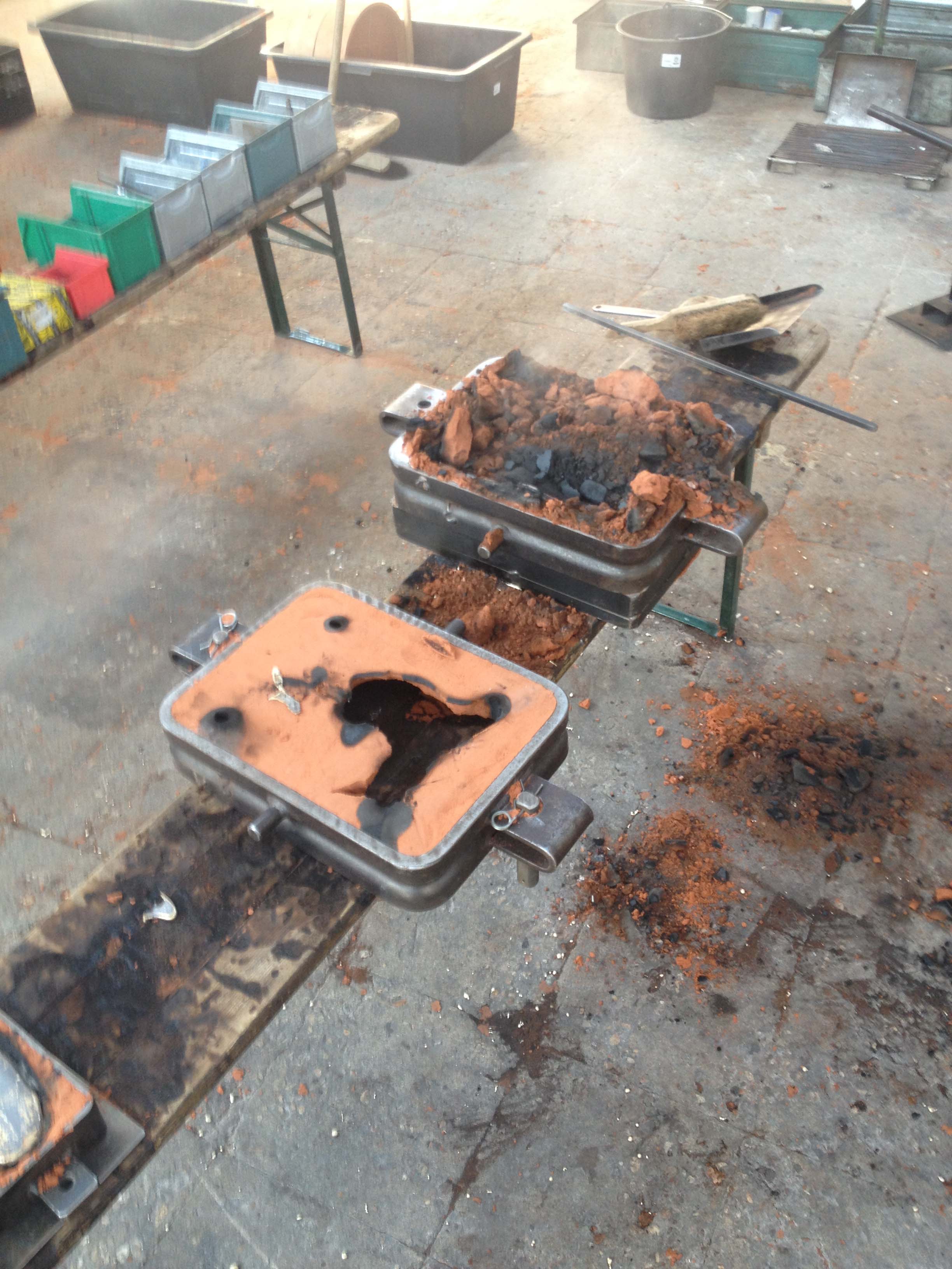
For my graduation project I designed a bronze foundry therefore I wanted to explore the possibilities of metal casting myself. Here fore I participated in a metal casting workshop organized by the Crafts Council in the Netherlands. In this workshop I had the possibility to create a metal casted site model of the location of my graduation.
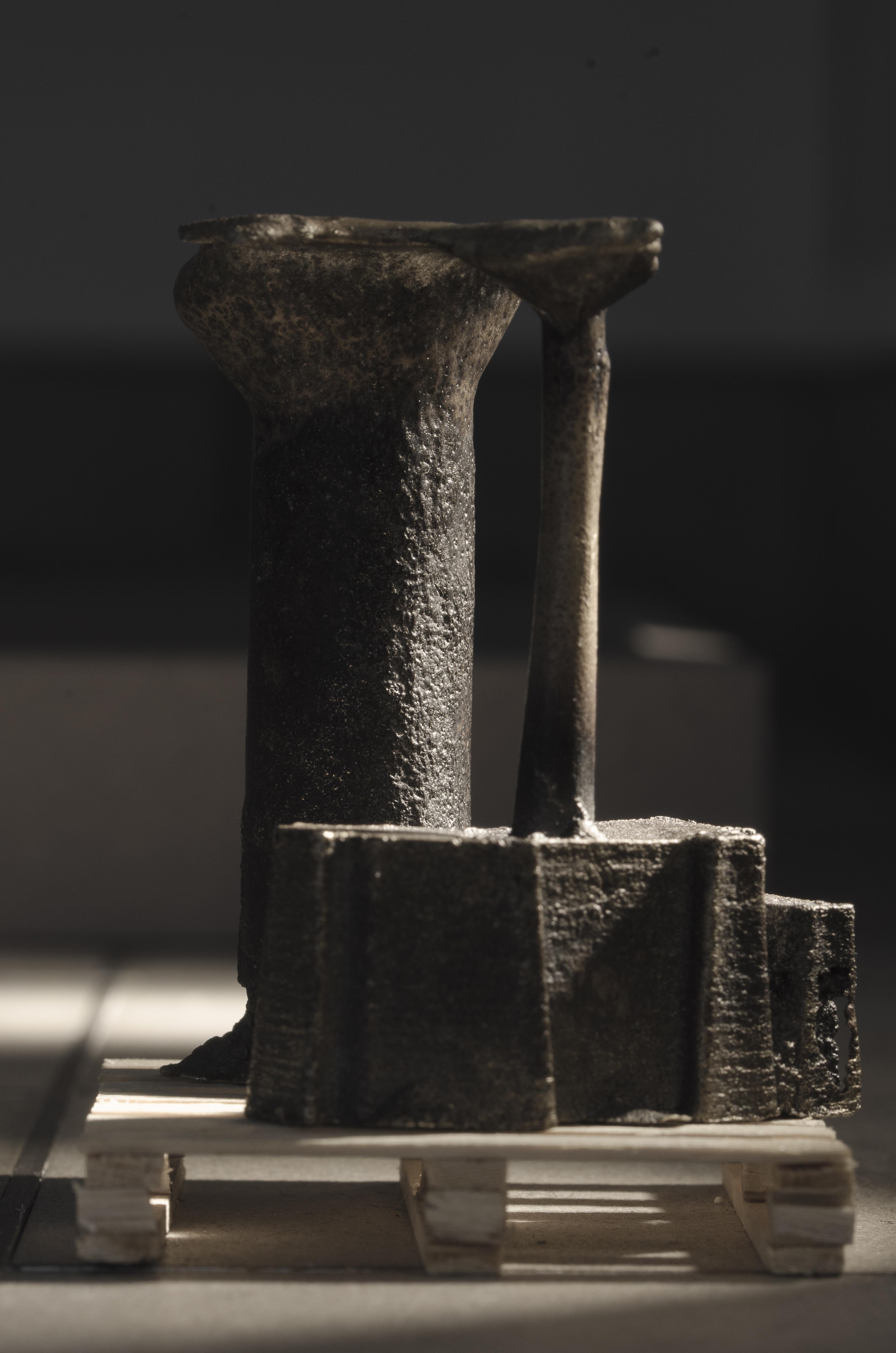
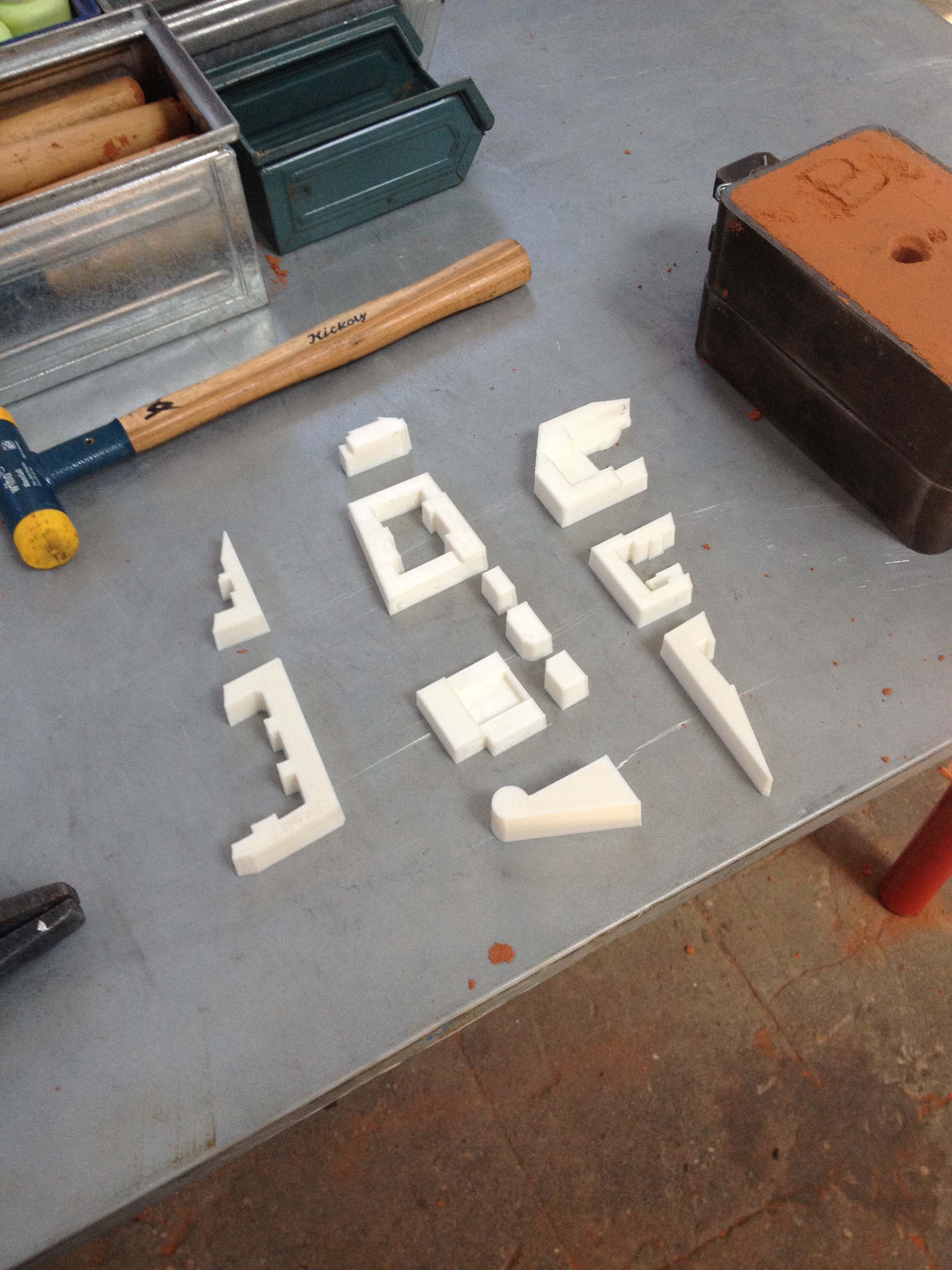
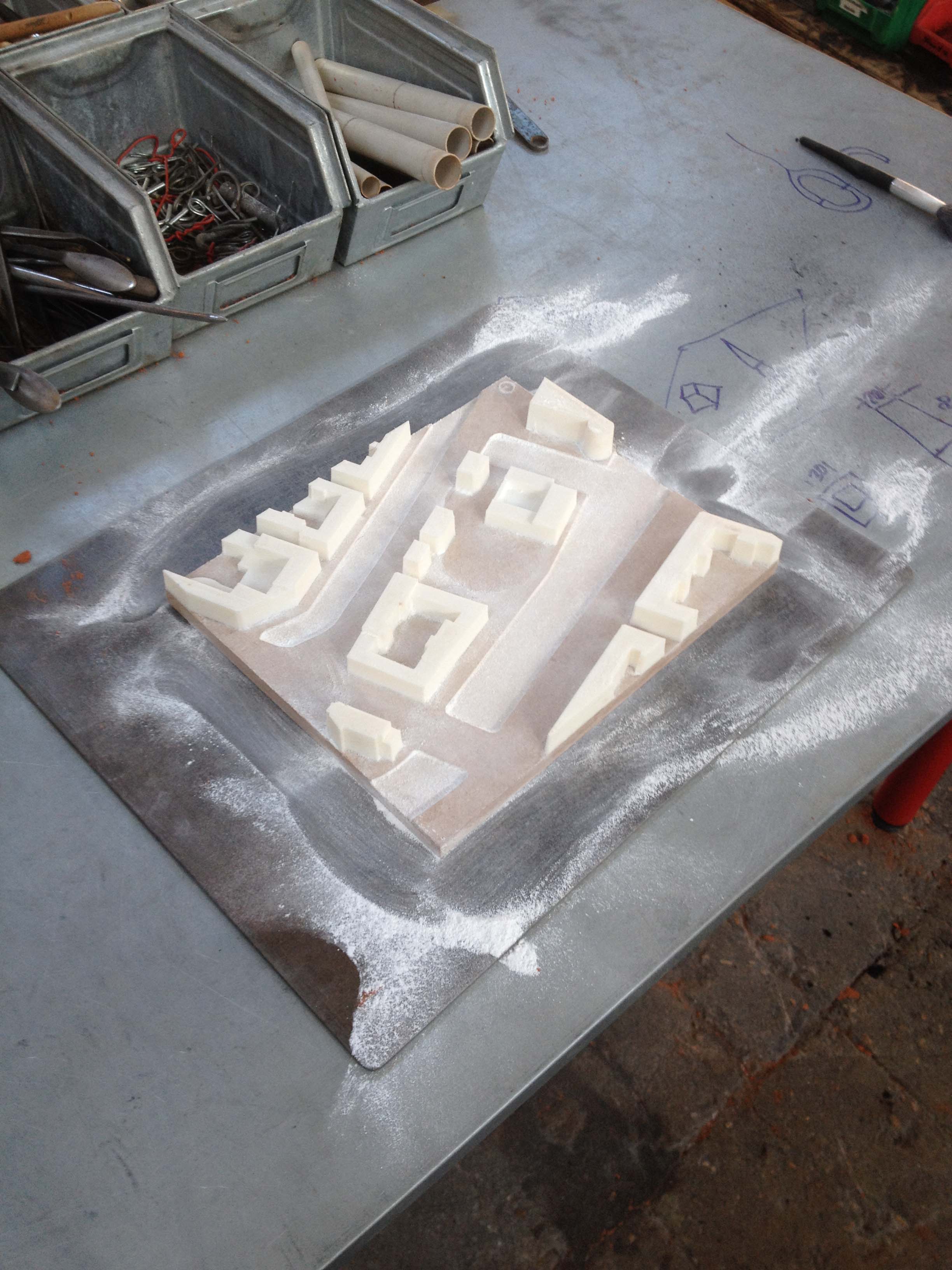
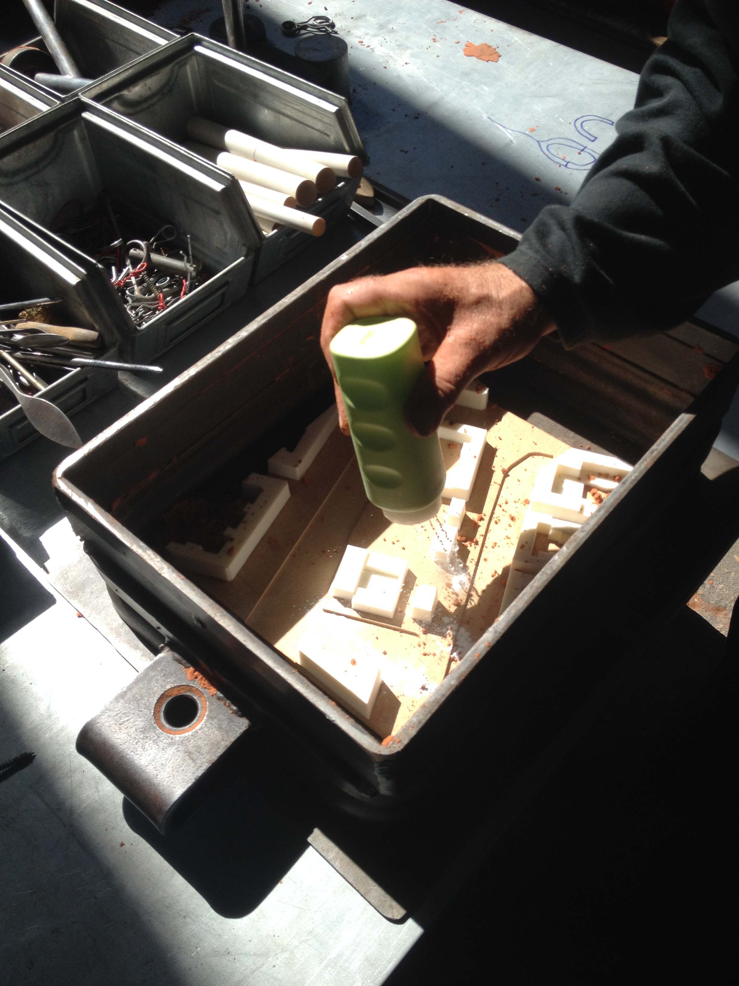
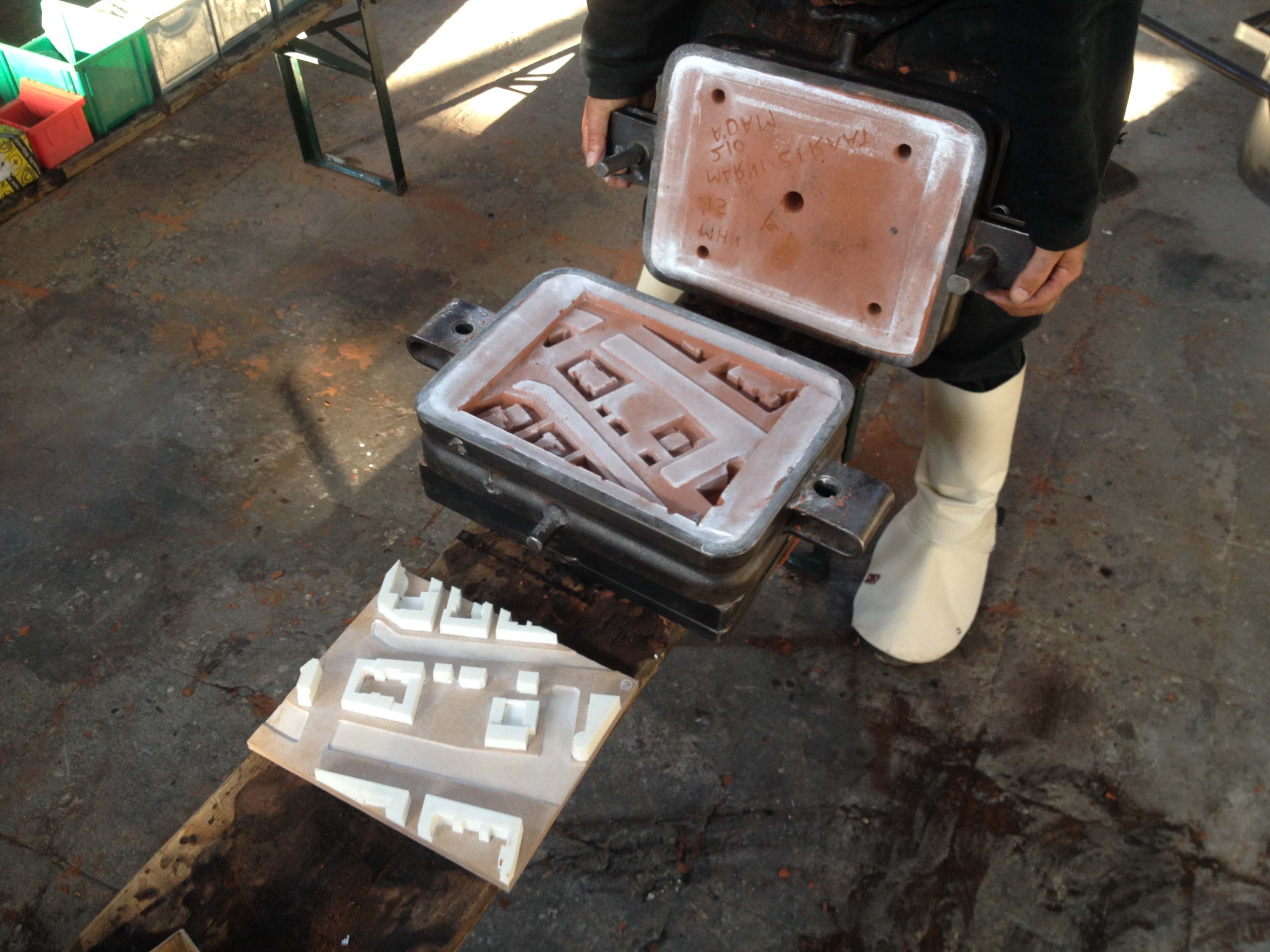
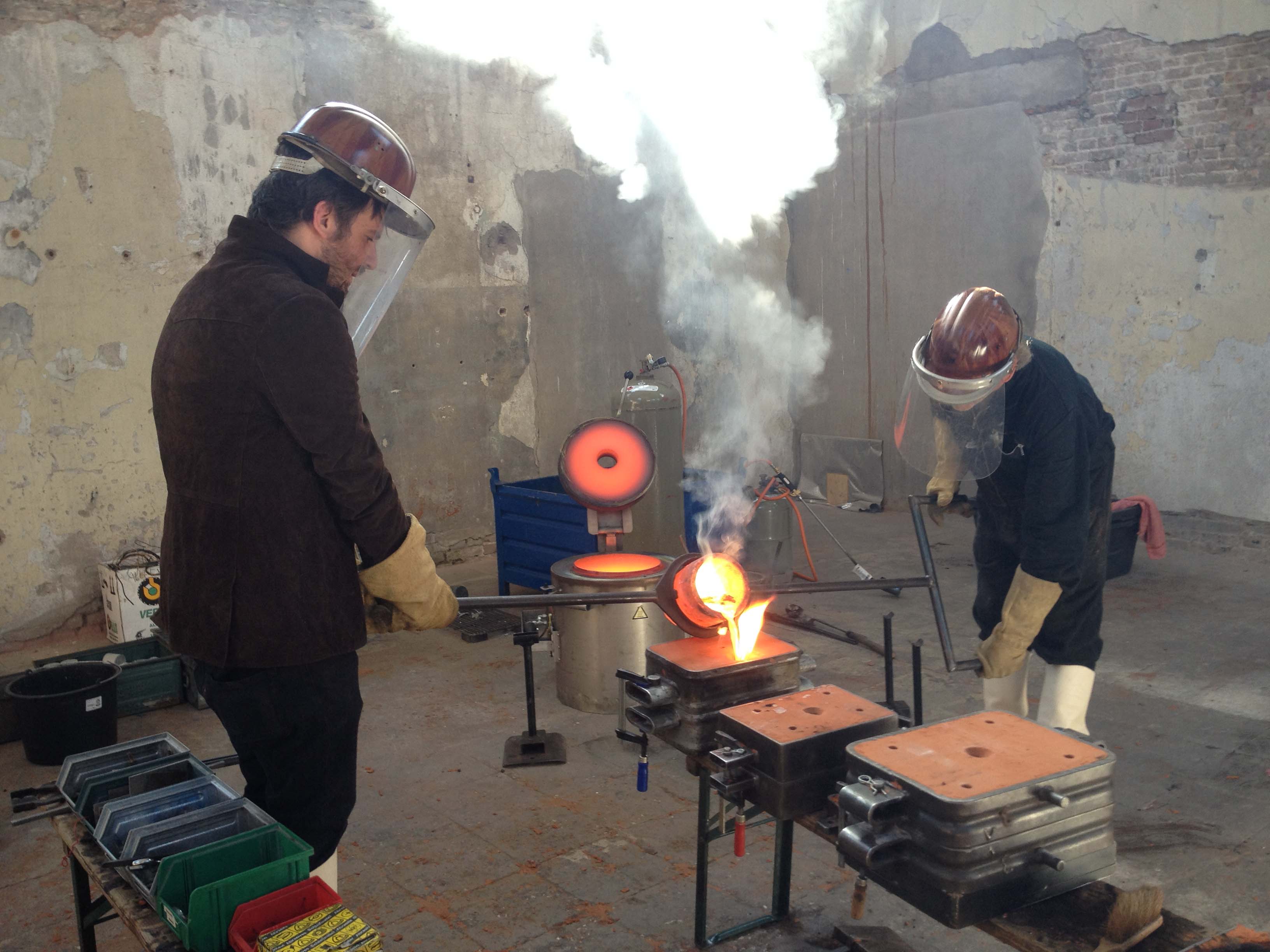
I researched the possibilities of combining an old craft together with new production techniques. Sand casting is an old production technique for the casting of metals. This technique uses sand mixed with oil to create a mold. But before the casting can start the model needs to be created first. I made the site model first by 3d printing all the surroundings buildings and gluing them to a CNC-milled base plate. This model was then used to create the mold where the brass was casted in to.
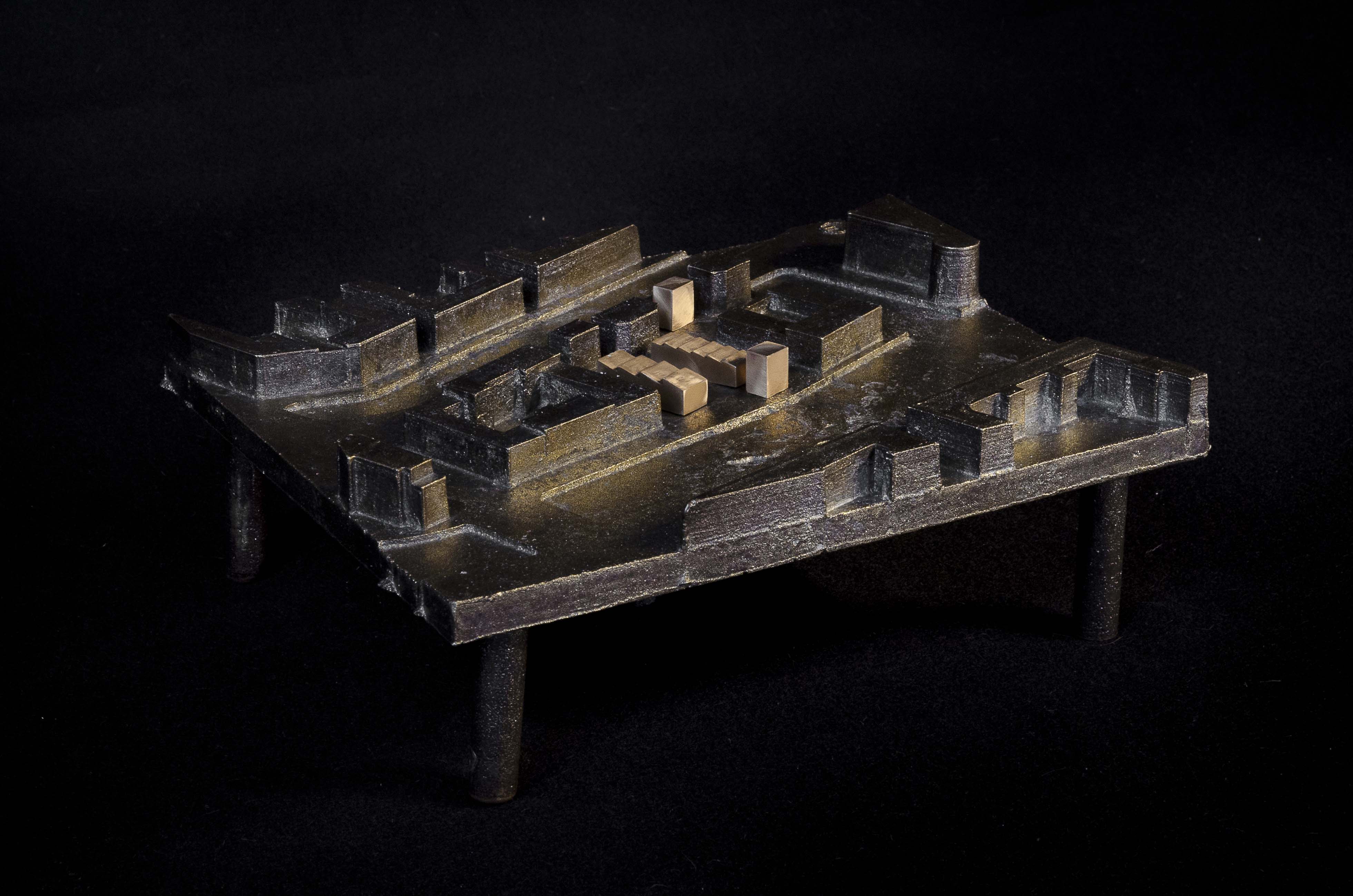
In the accompanying pictures and movie you can see the process starting with the 3d printed objects to the finished model. The site model is in a 1:1000 scale and made out of solid brass. The four shinny bronze blocks is the final design of my graduation project. The ‘’legs’’ underneath the model are the air outlets of the mold. I decided to leave these on the model as a reference to the casting process.


Movies:
-Crafts Council video:
https://vimeo.com/132807849
-Sand casting a 1:000 architectural scale model in solid brass:
https://youtu.be/SIZ96zbk2D0
Posted in Appearance, Craft, Moulding & Casting, Projects
Tagged Max Hart Nibbrig, photography
The following text is how Tiwánee van der Horst describes her graduation project in relation to the modelling techniques she used to accommodate a time lapse movie.
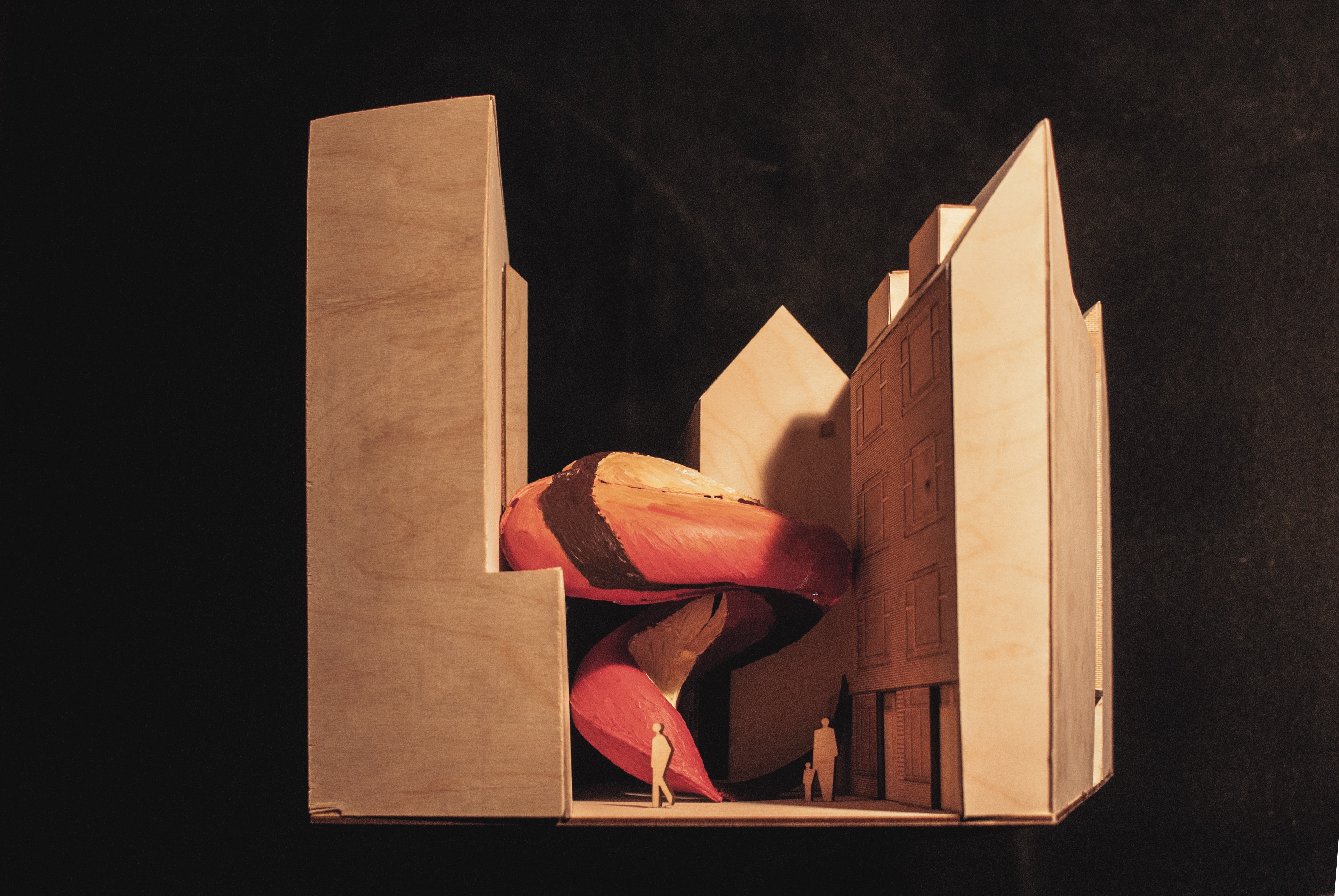
The design for my graduation project was an organic structure where the shape was a result of a three dimensional translation of painterly movements and textures within a narrow alley. With my final model the aim was to show the designed building process through a time-lapse (see movie). For this it was needed to make a transparent surface onto which I could paint, so in the movie it would look like it was extruded in mid air.
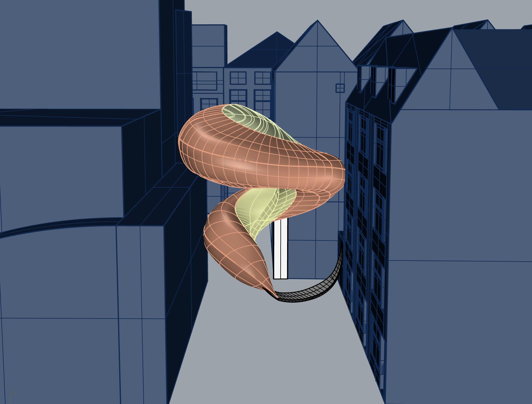
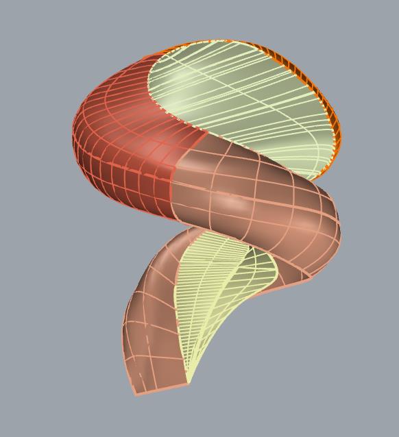
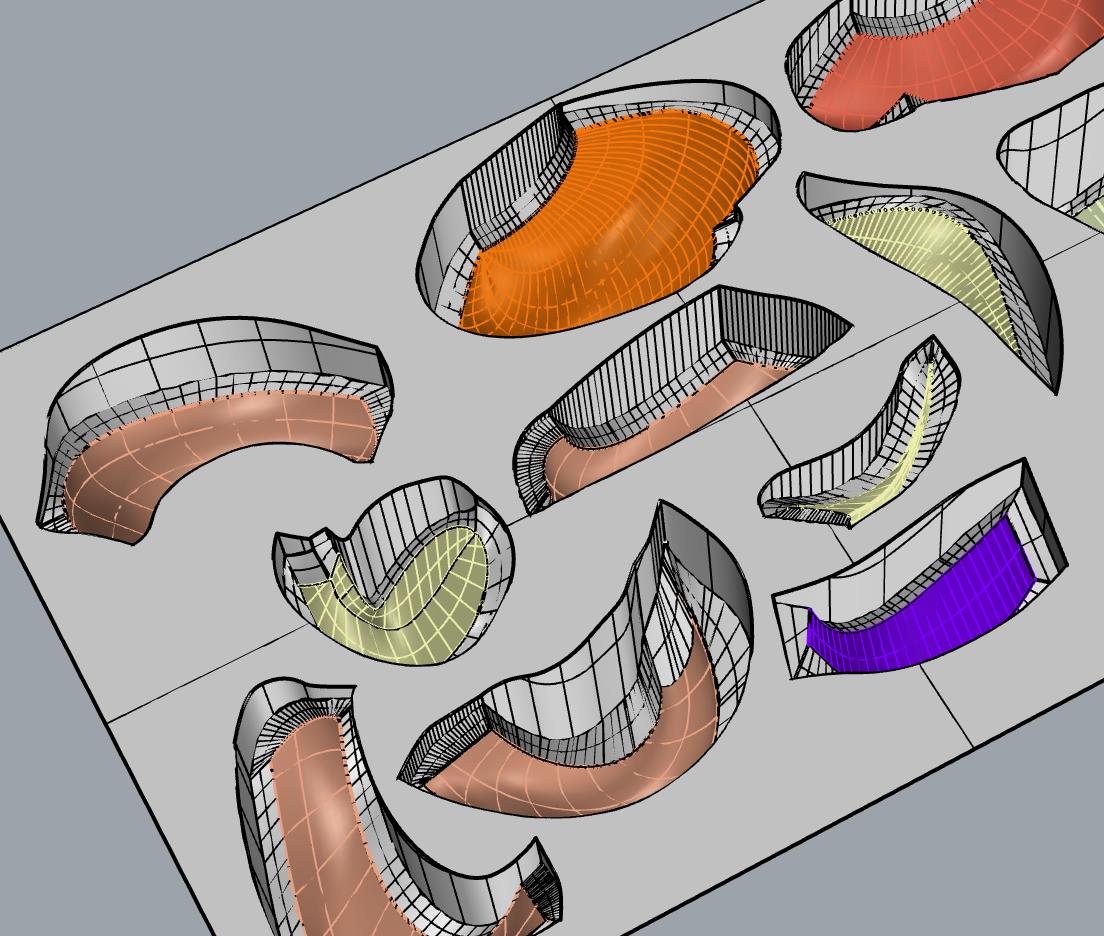
The options were either to 3D print the complex shape with a transparent filament or to deep draw with transparent Vivak. However the filament would never be entirely transparent. Therefore I decided to use transparent Vivak for deep drawing. For this it was necessary to make a mold through CNC milling. I divided the design into separate parts, which could then be laid out horizontally for deep drawing, after which all the parts could be glued together, creating the transparent paint surface.
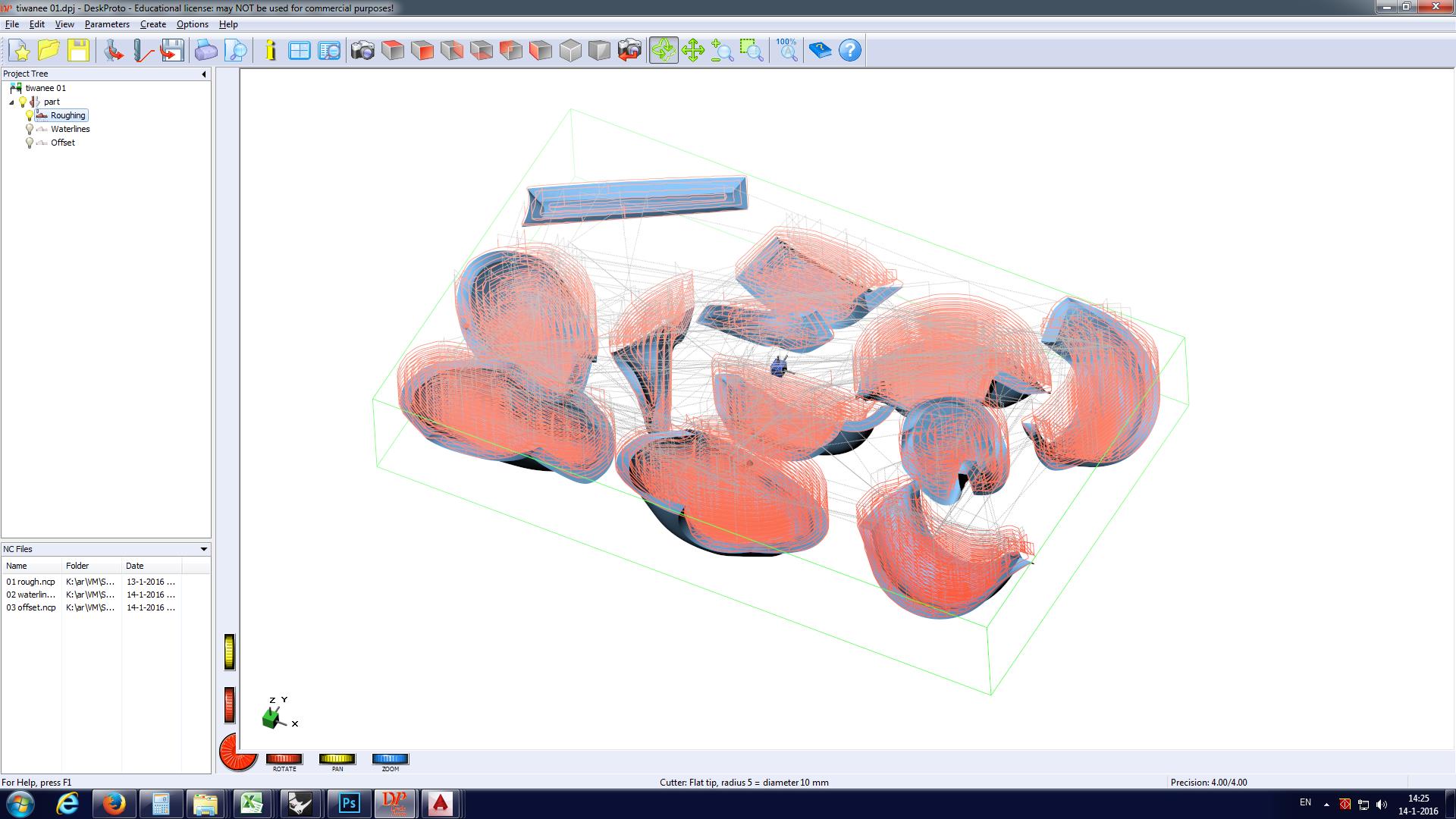
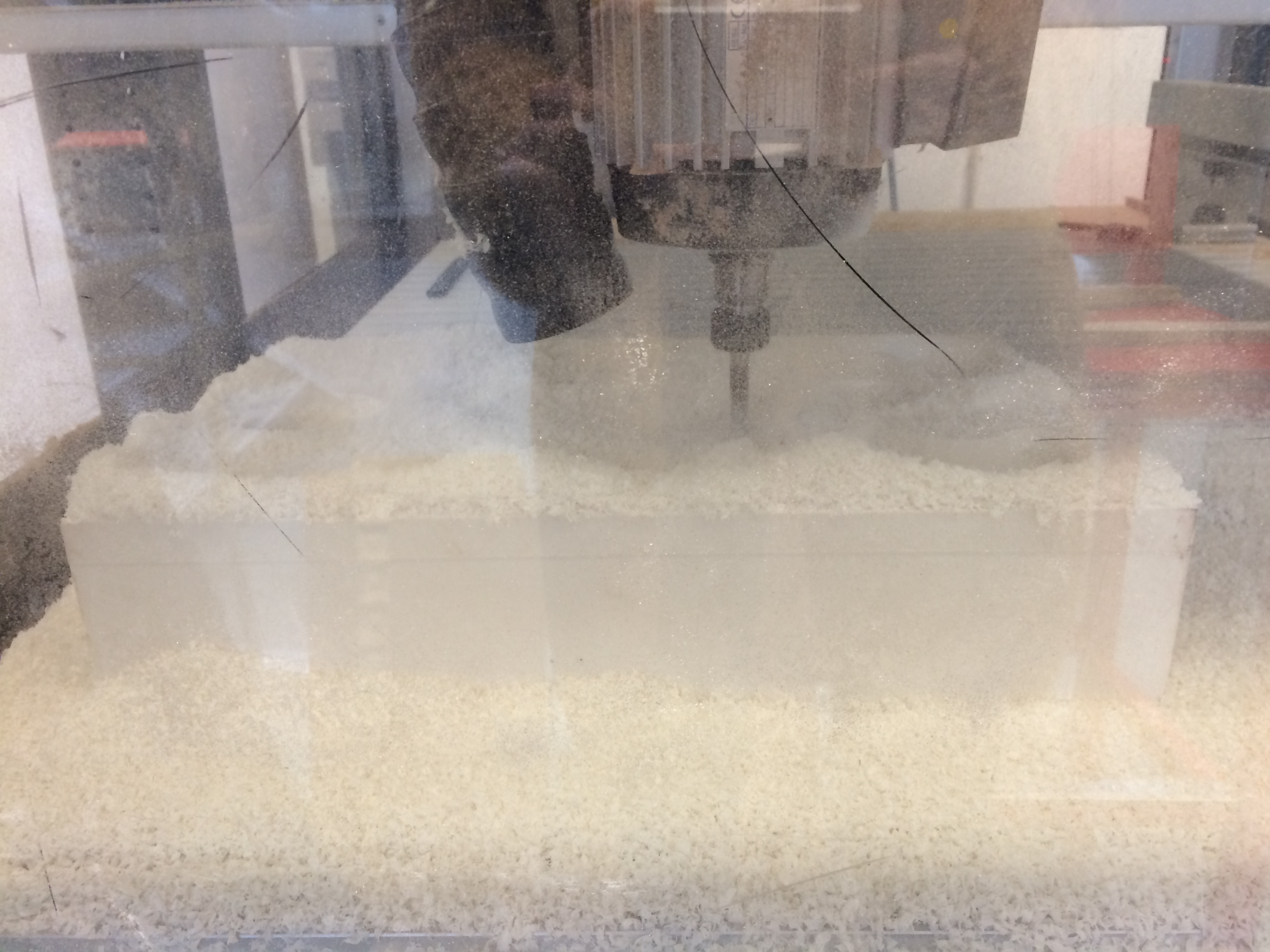
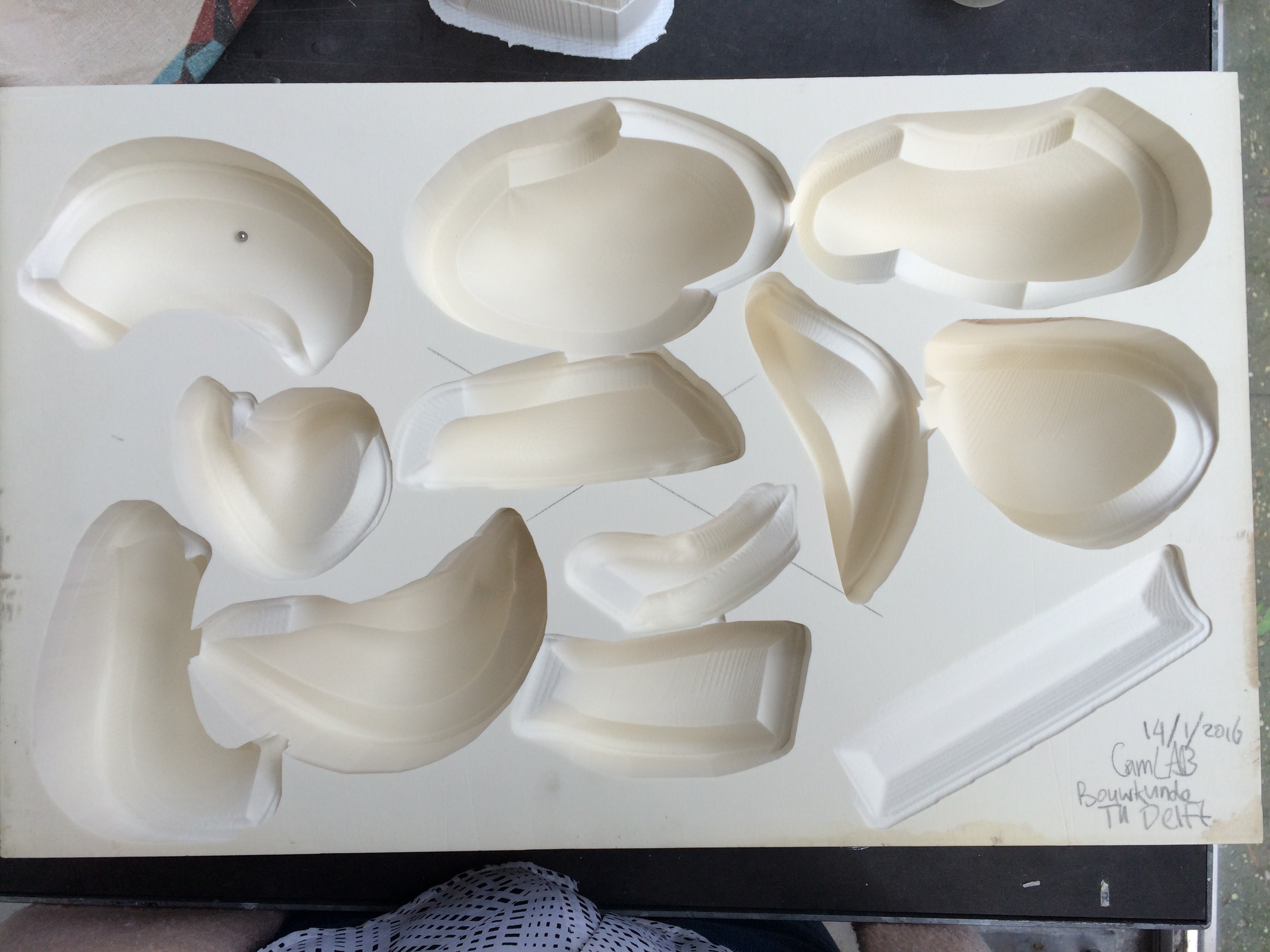
The rhino file was prepared for the CNC milling process by the CAMlab. Because the deep drawing shows every single inaccuracy of the mold we let the CNC milling machine run multiple times until a smooth surface could be made out of the material. To prepare the mold for the deep drawing process it is necessary to create air holes through the block from the deepest points in the mold. To find these points I used a little ball from a bicycle wheel. After having found all the deepest points, the next step was to drill the holes through the block. The holes needed to be as small as possible other wise the holes would show in the surface of the Vivak. As the block was about 11 cm high it was not possible to drill through the block with the 1,5 mm drill. From the back I used a drill with a larger radius. However this process resulted to be to tedious and to risky. We needed to find another way.
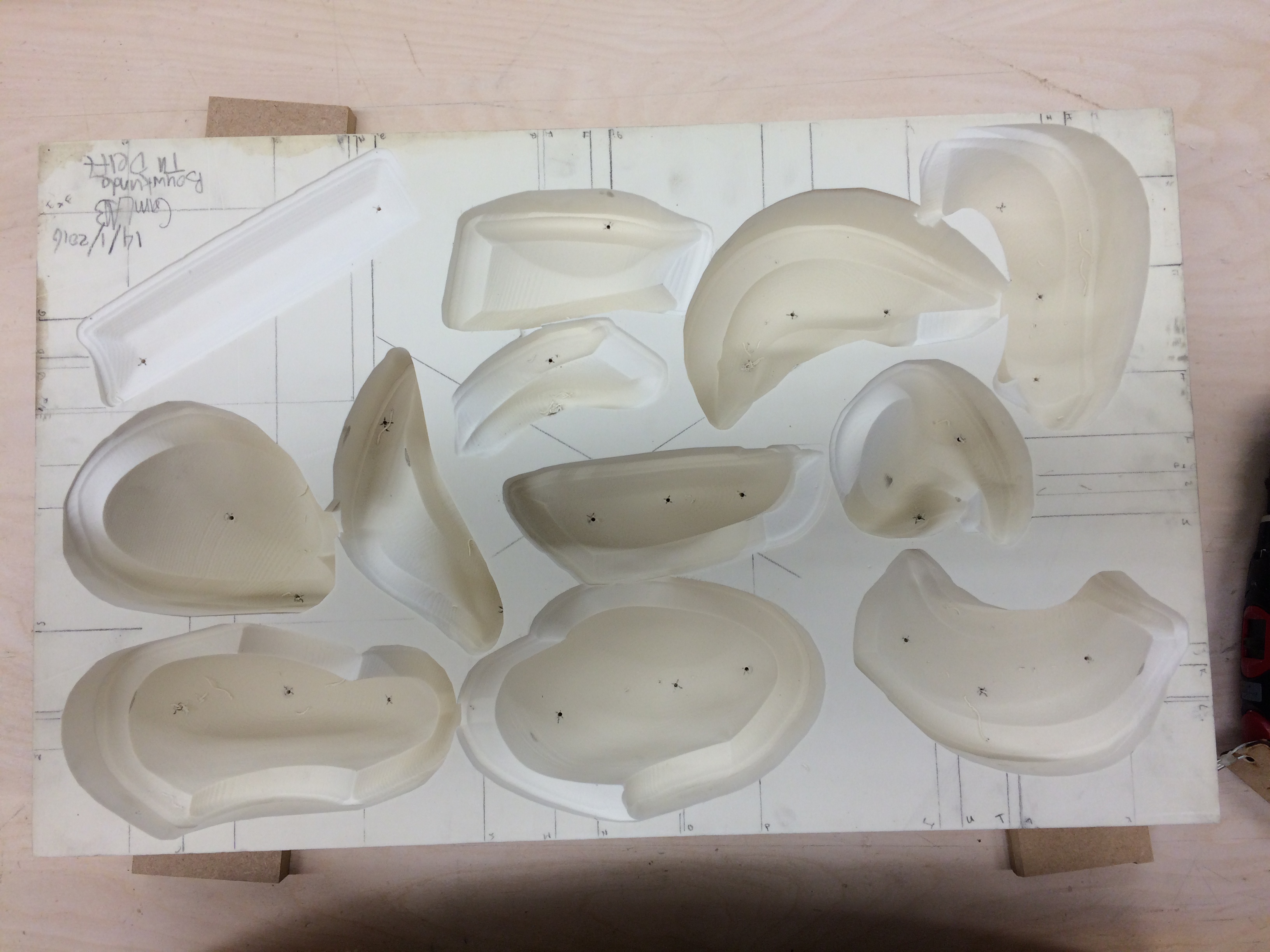
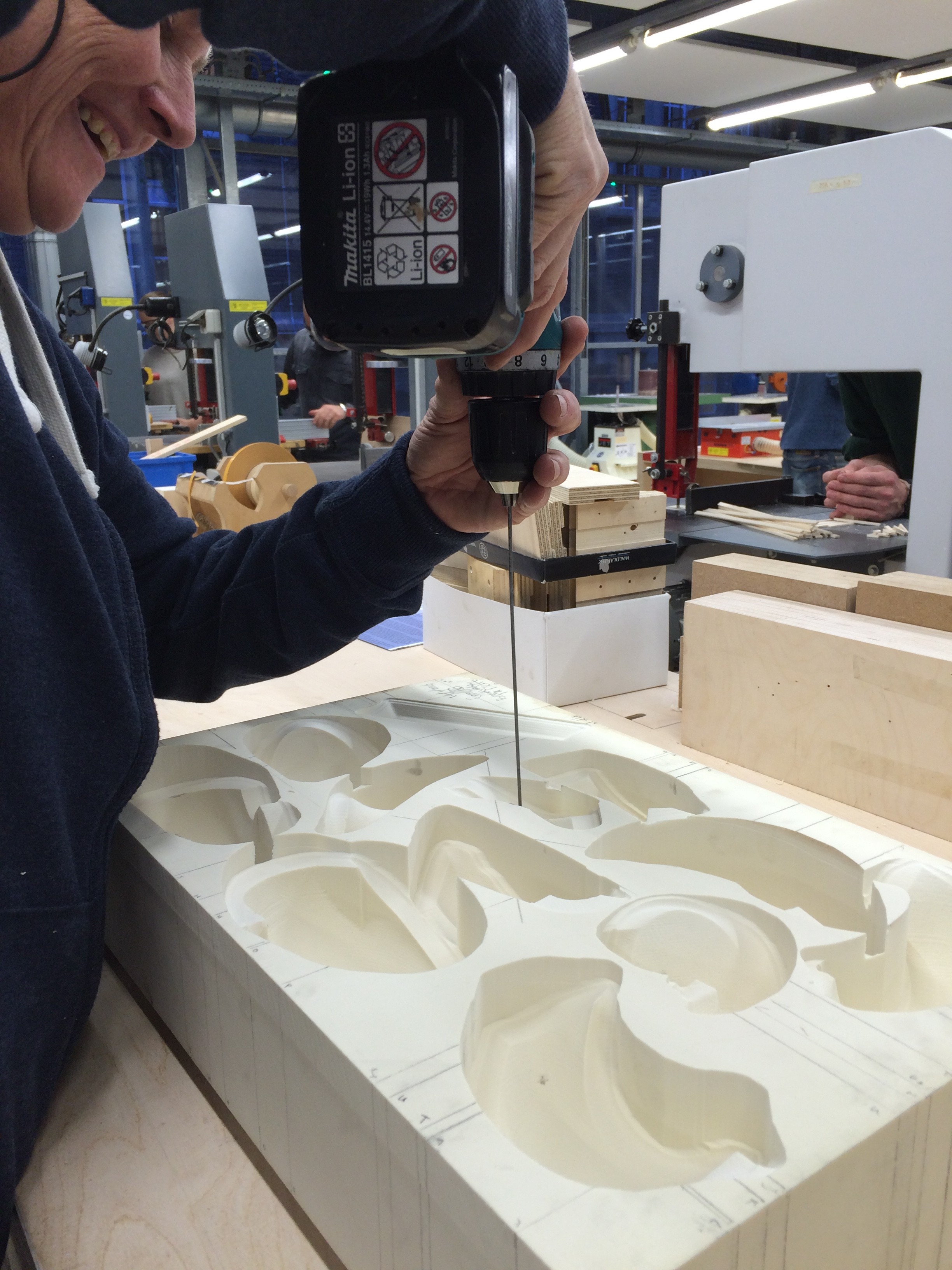
With the help of the staff of the modeling hall we found a bicycle spoke with which we could drill small holes through the entire block height.
With all the air holes drilled and the corners smoothened it was time to give the deep drawing a try, but the block was too high and too large.
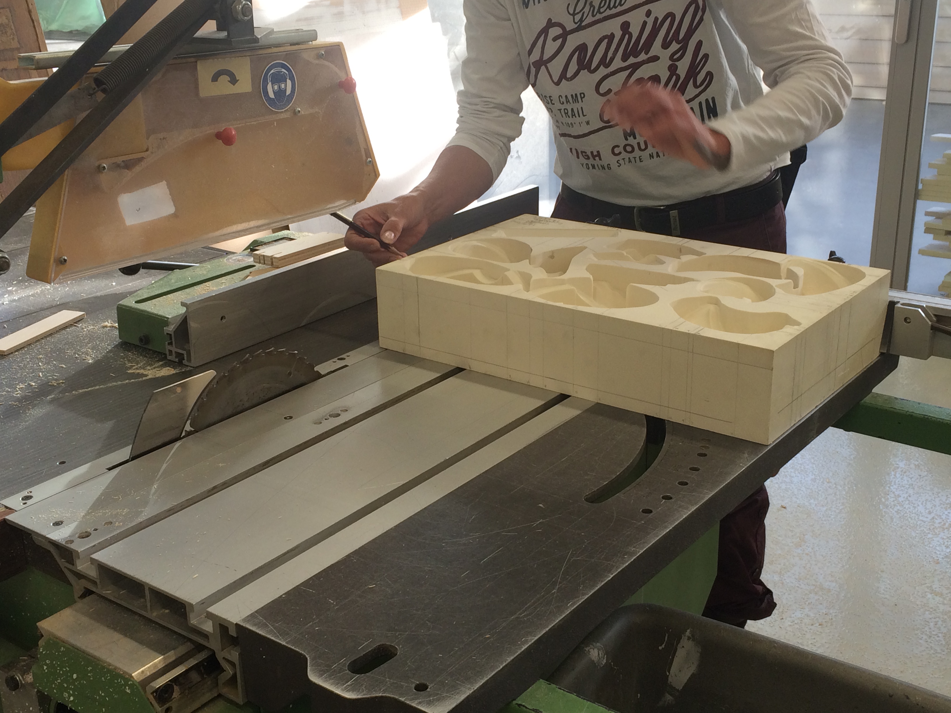
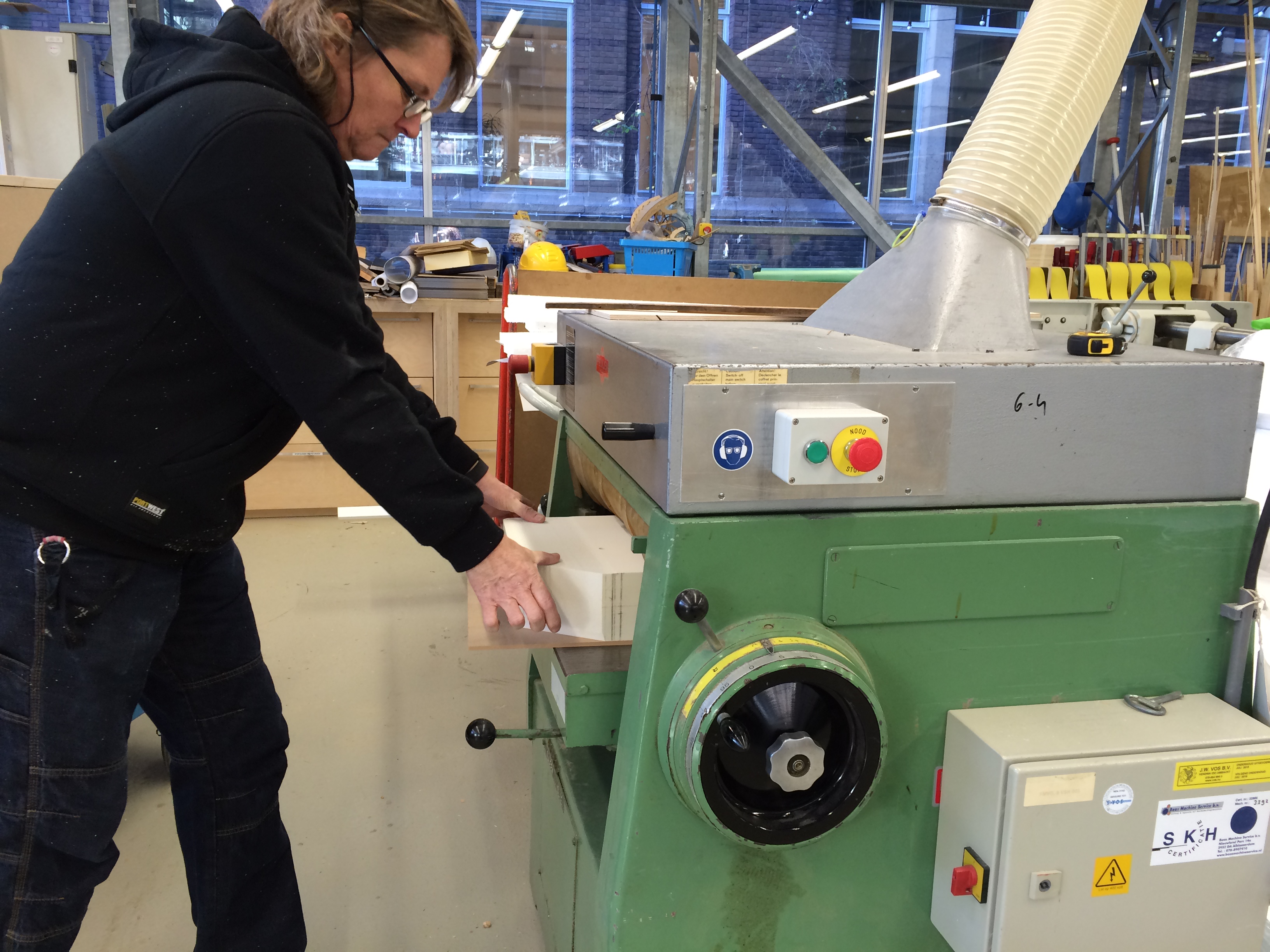
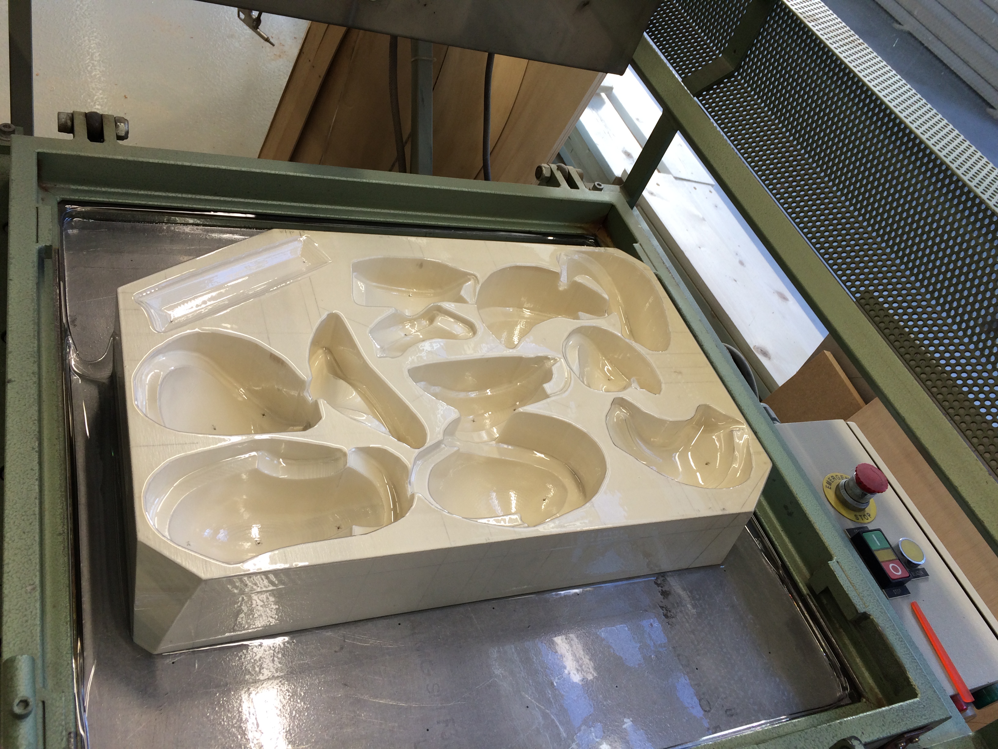
To reduce the height by 14 mm we used a thicknessing machine and attached the block to a board with double-sided tape to insure the block to stay in place. Finally we succeeded to fully deep draw the block. Next up was the removal of the Vivak from the mold, by blowing air through the holes from the back.
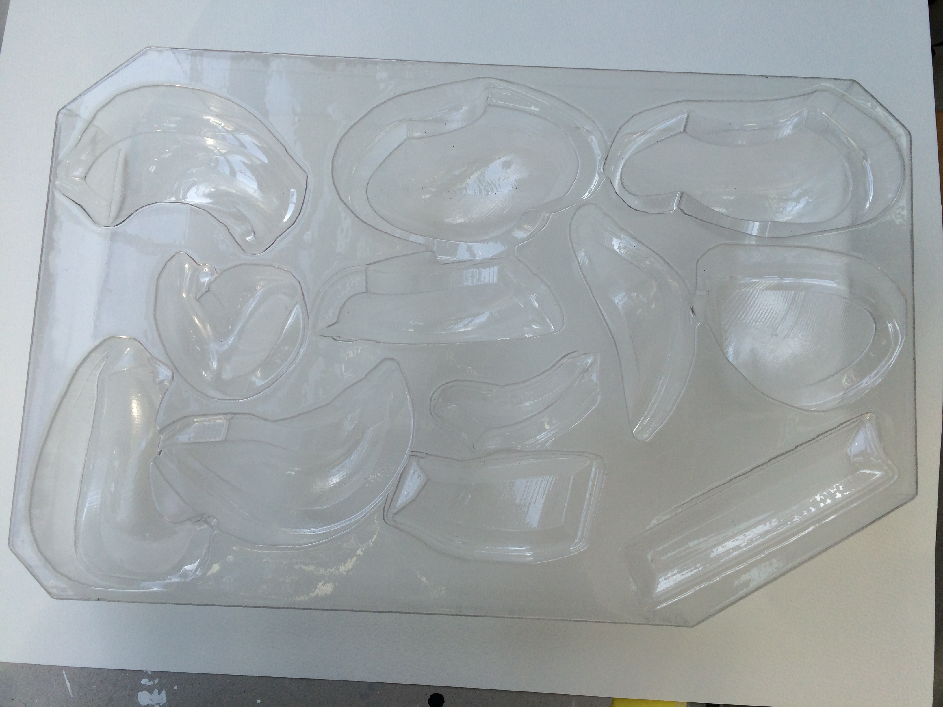
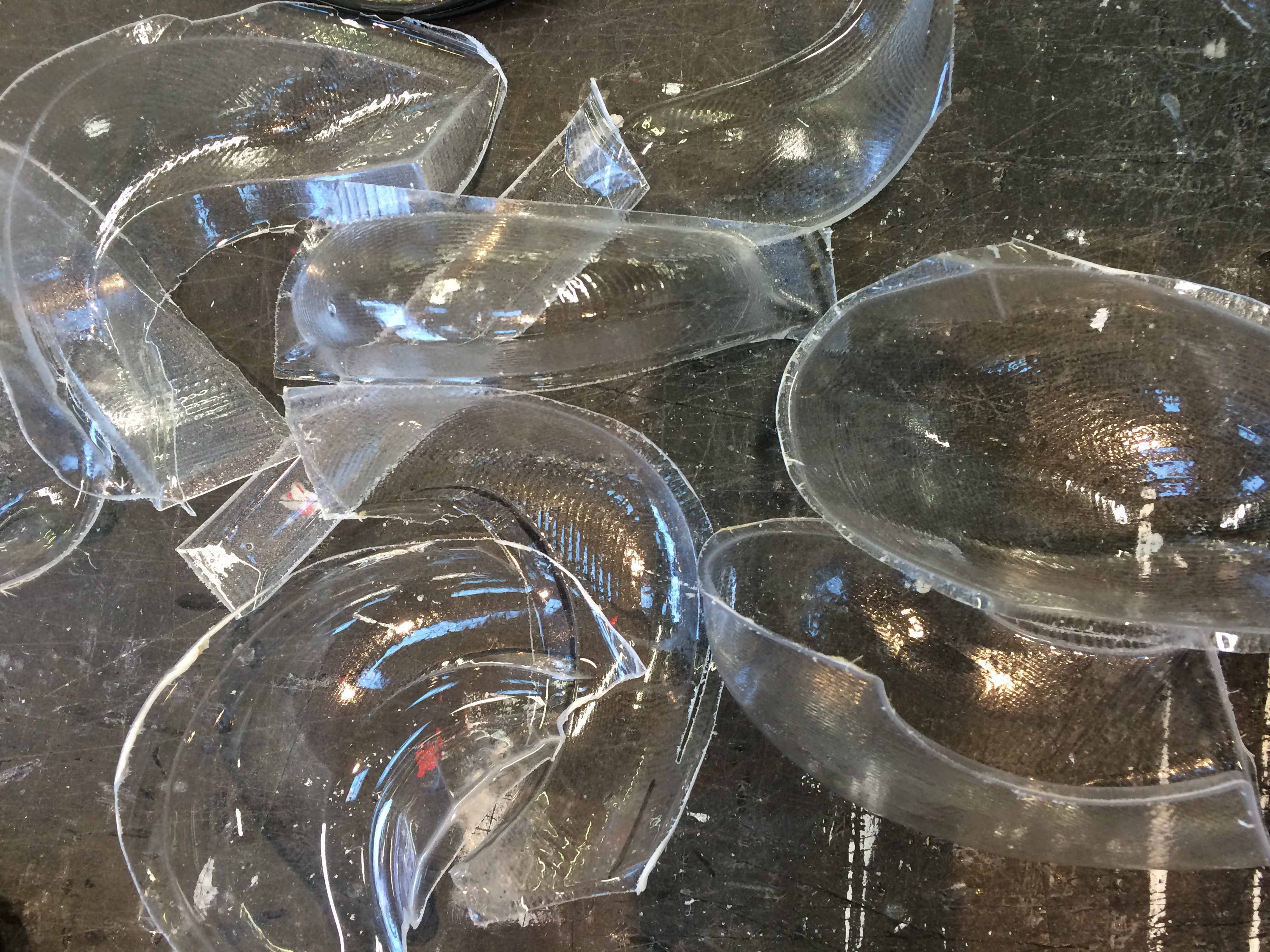
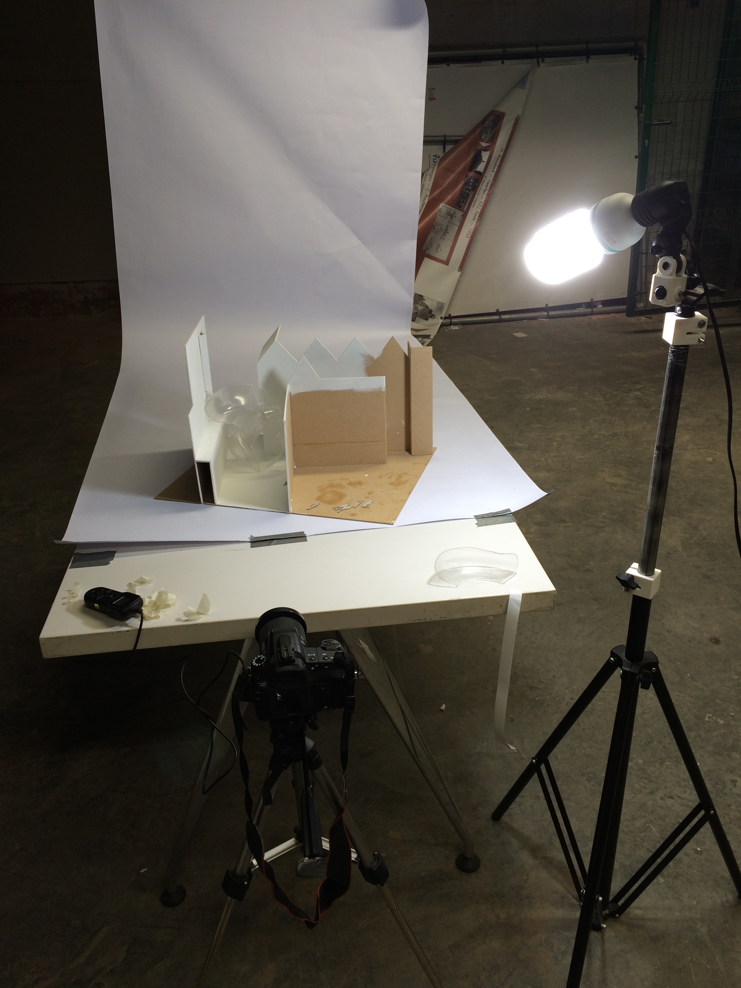
I removed the surfaces that I needed for the model using a saw and utility knife. After attaching all the pieces together it was time to start the painting process. I set up the camera and lighting, prepared the color palette and started painting. The result of which is shown in the movie, giving a first impression of what a building process might look like when architecture becomes as painting.
The following text is how Nadia Remmerswaal describes the project.
During my graduation project I have focused on designing a safe housing solution for the Kampung of Indonesia. Making up 80% of the Indonesian cities, the Kampung are housing areas that are famous for their informal, self-build, organic growth that houses the low-to mid-low income city dwellers. It is paramount for these mega-cities like Bandung to be densified, but research shows that insufficient building knowledge is available in these Kampungs to construct higher than two storey buildings.
In my research I have focused on using new technology, like CNC milling, to design a durable, affordable, customizable and above all safe building system that enables the local community in these informal areas to build up to four storeys high.
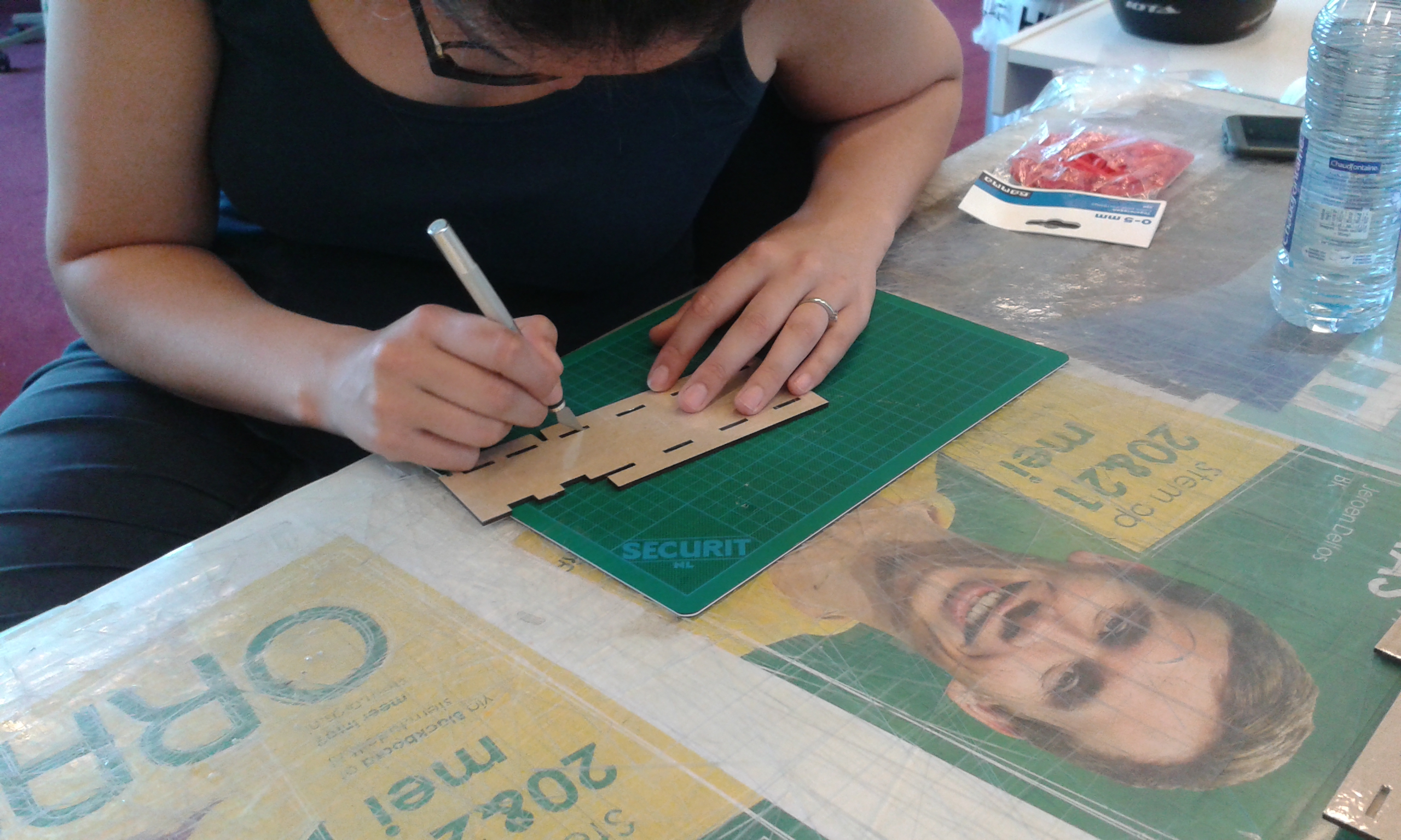
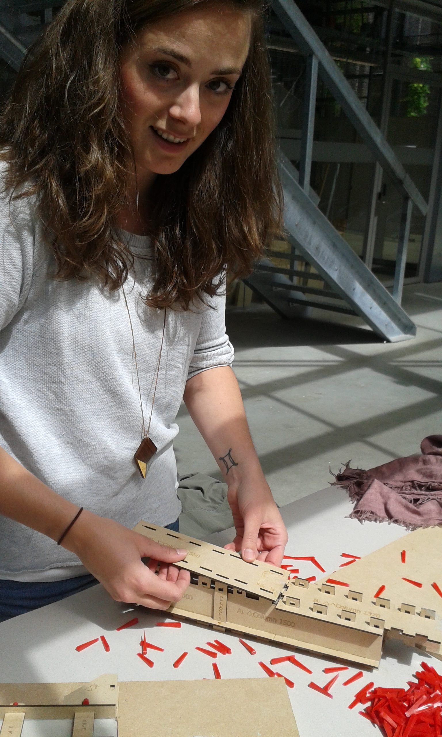
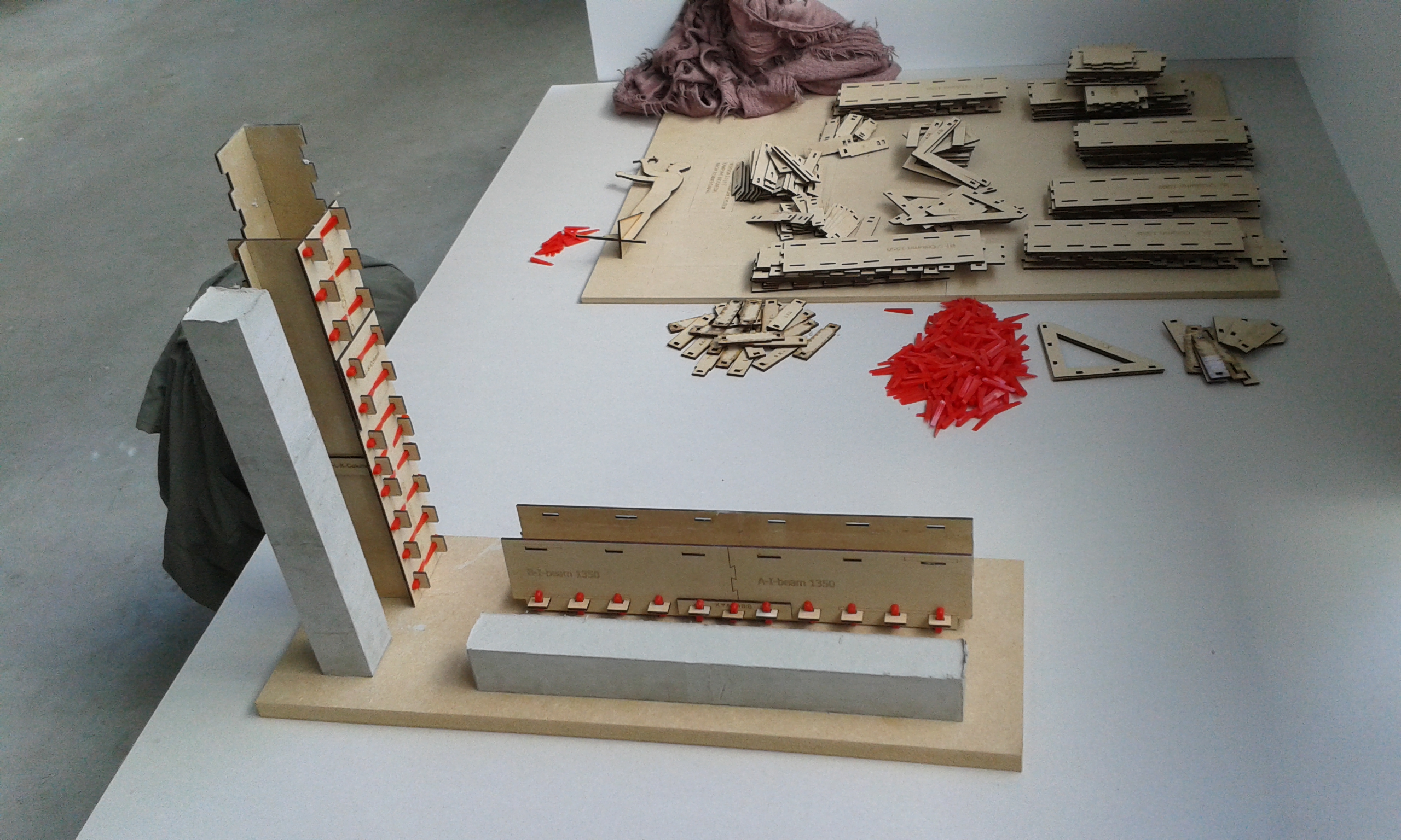
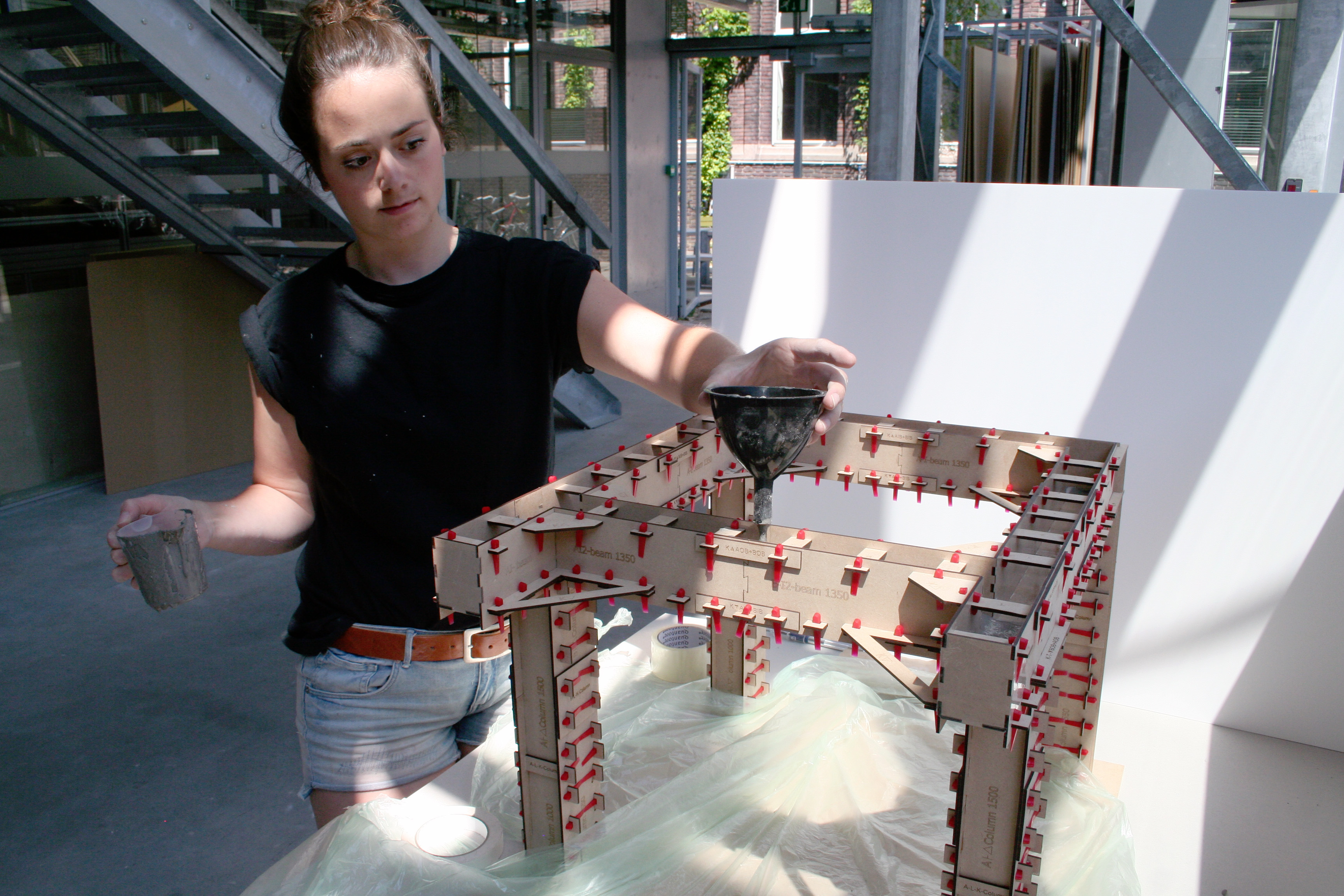
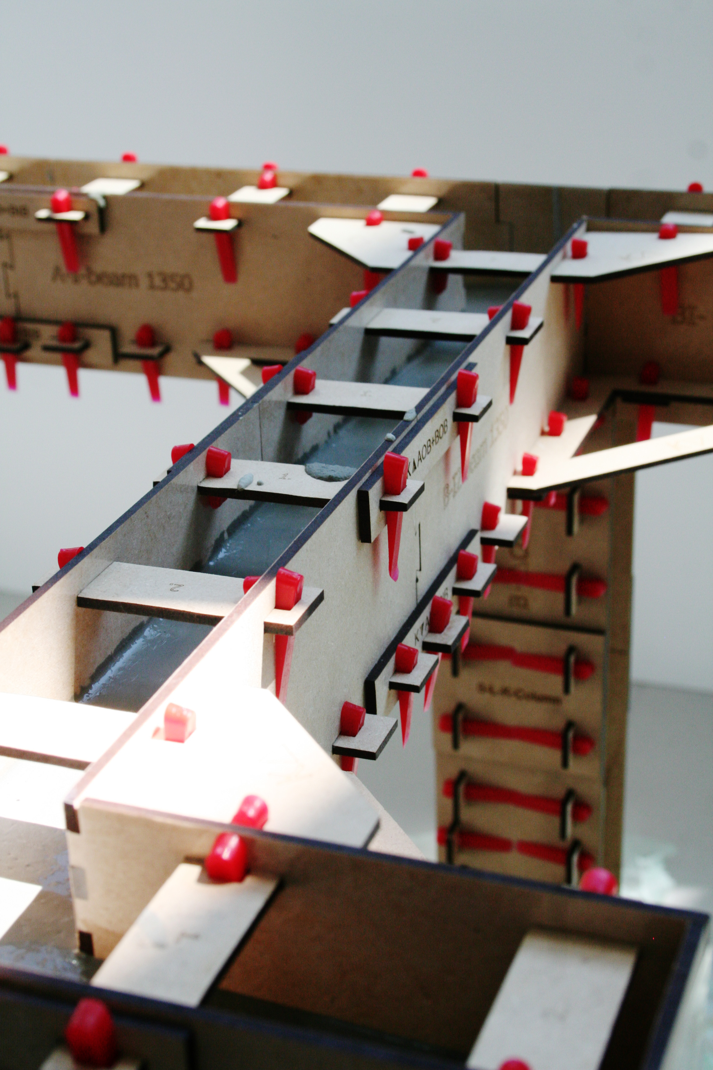
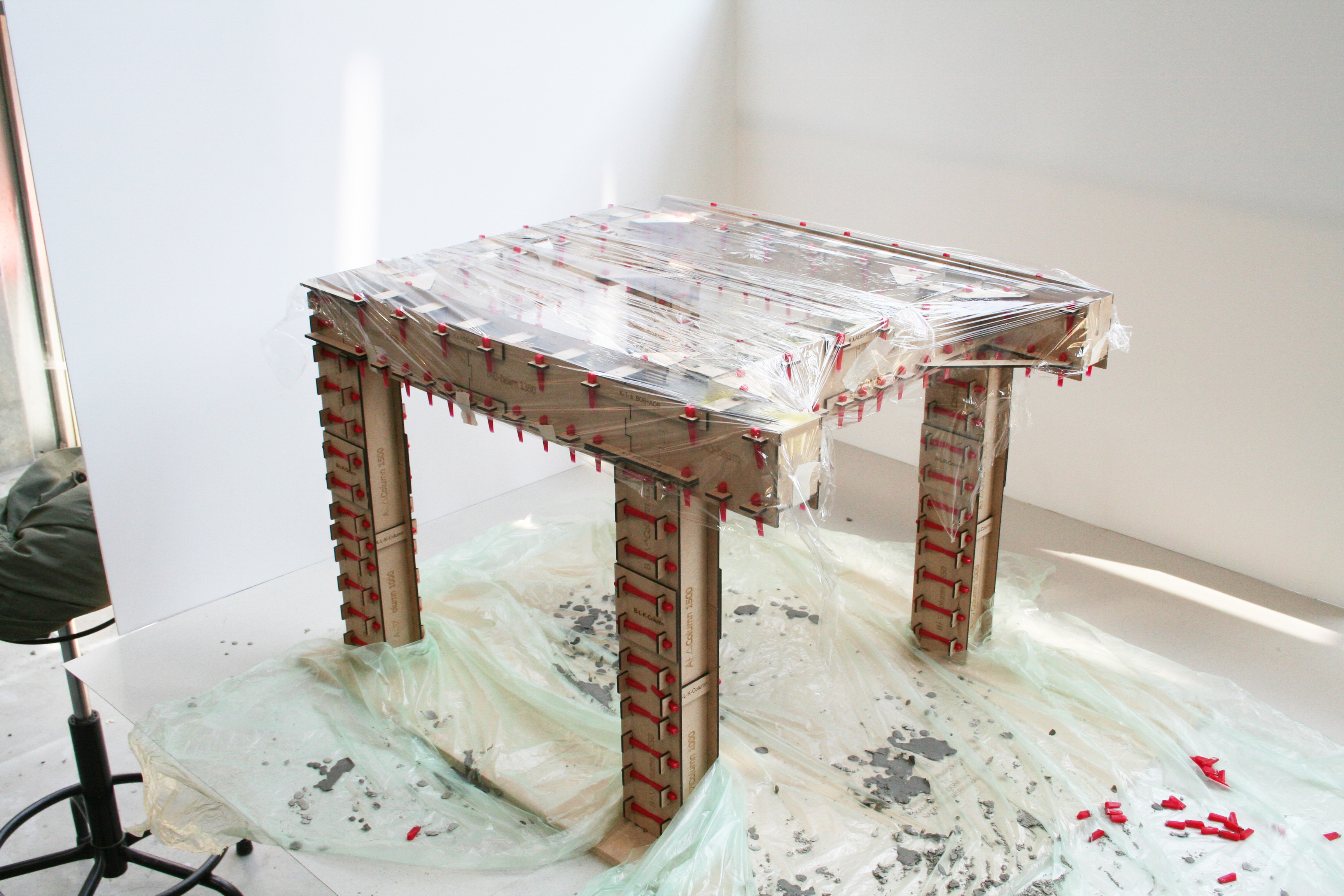
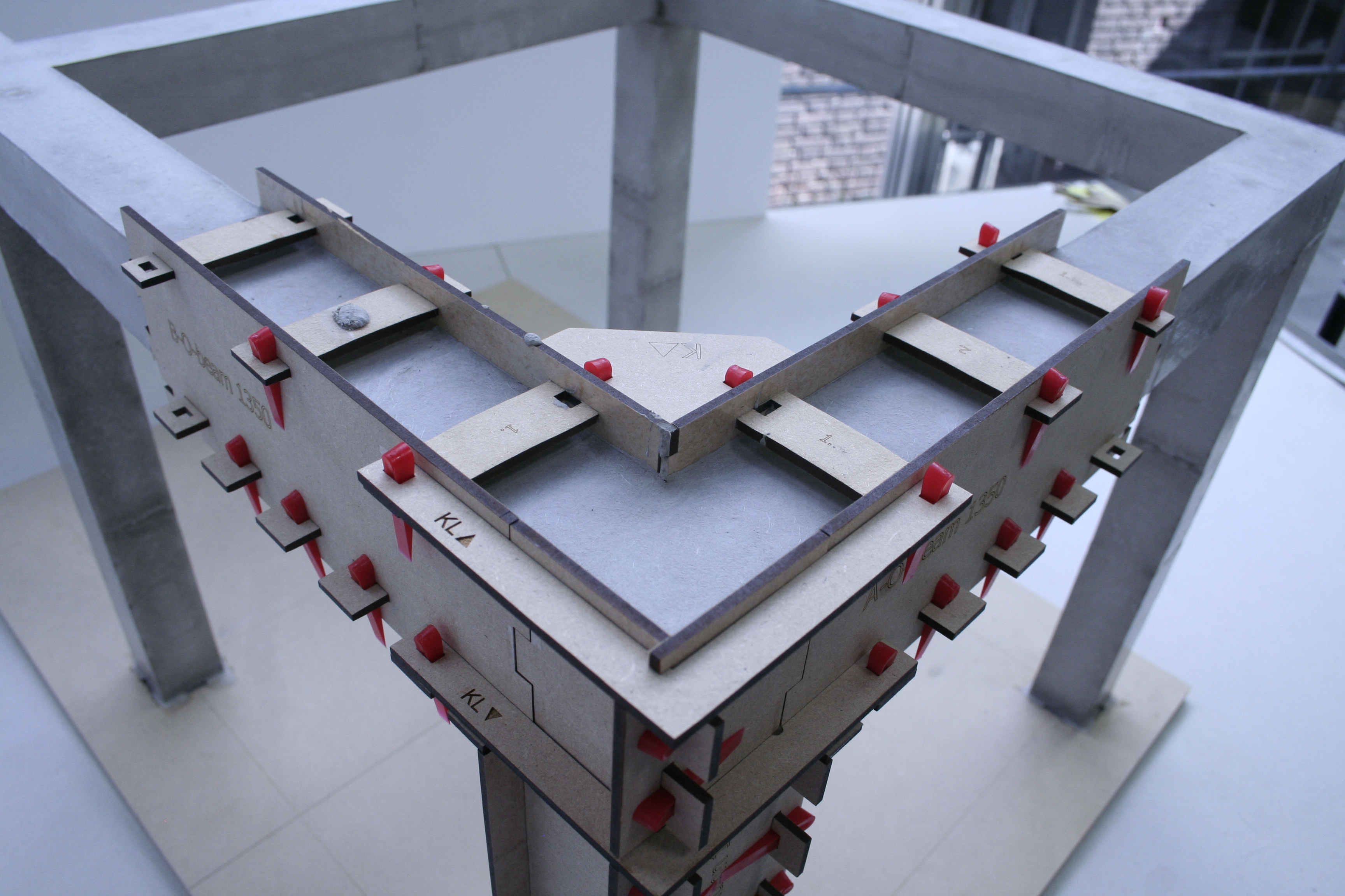
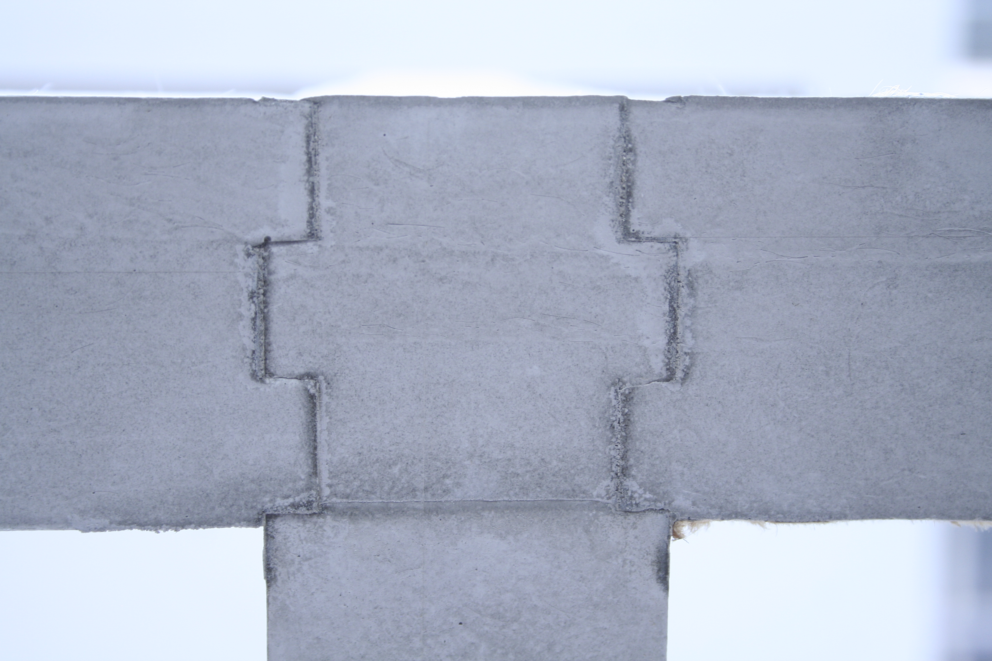
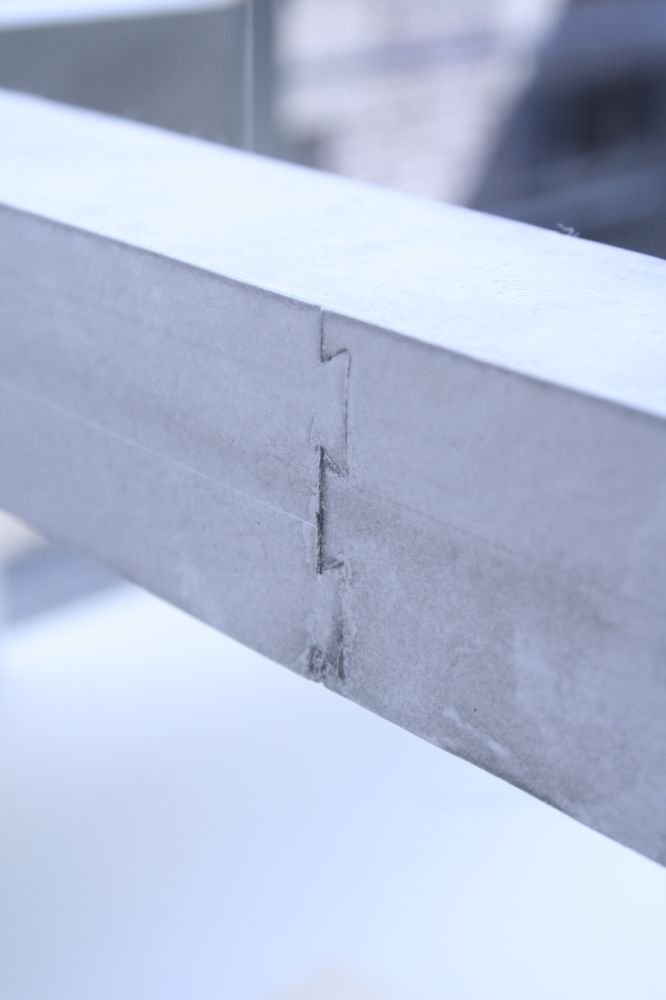
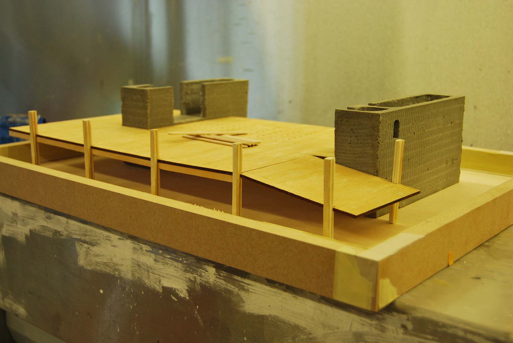
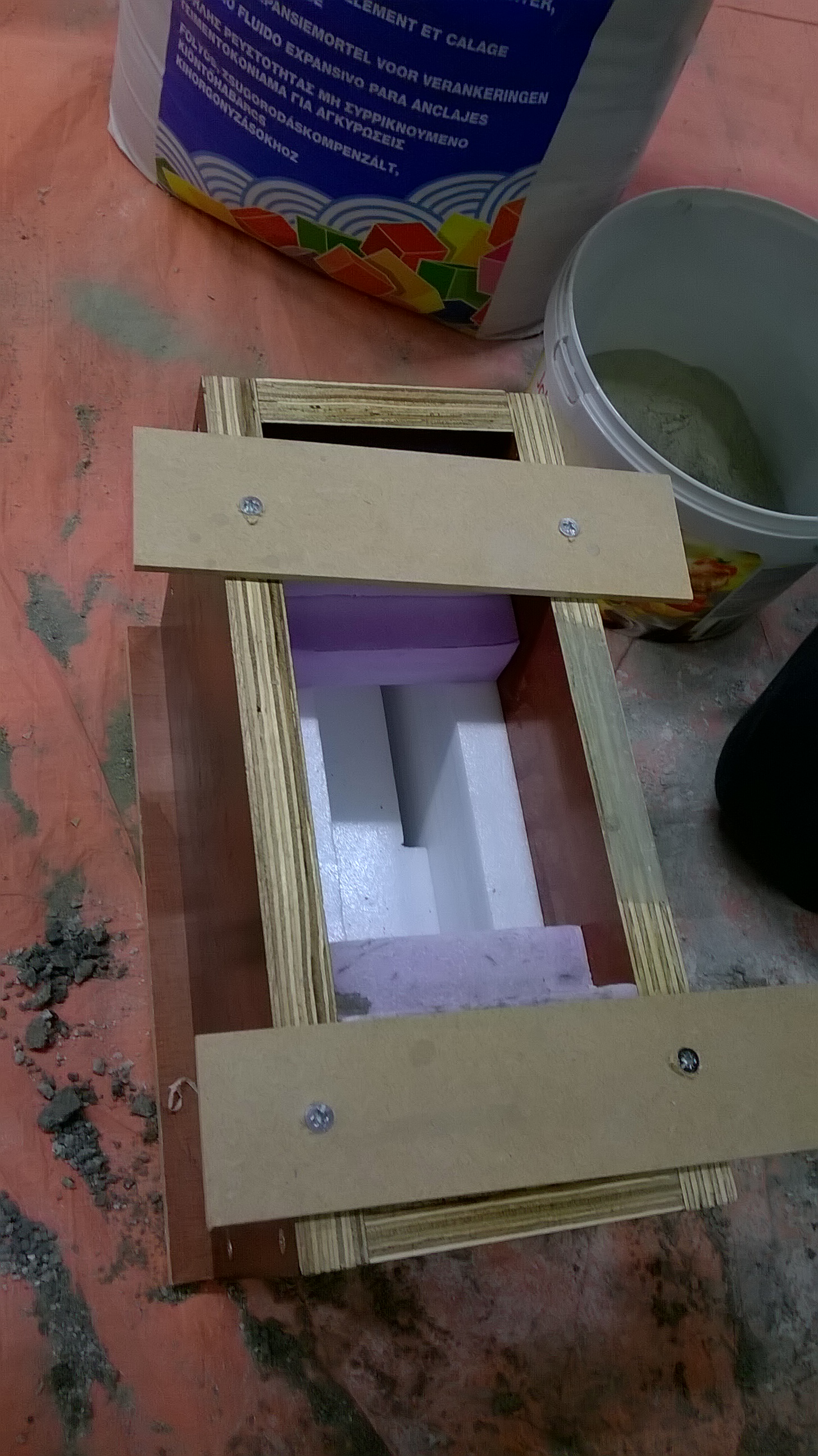
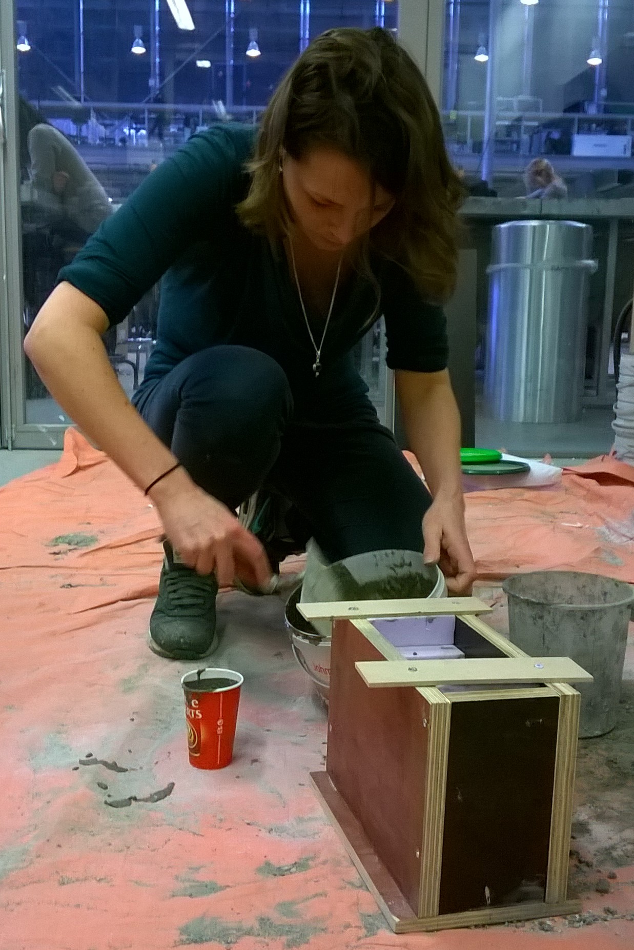
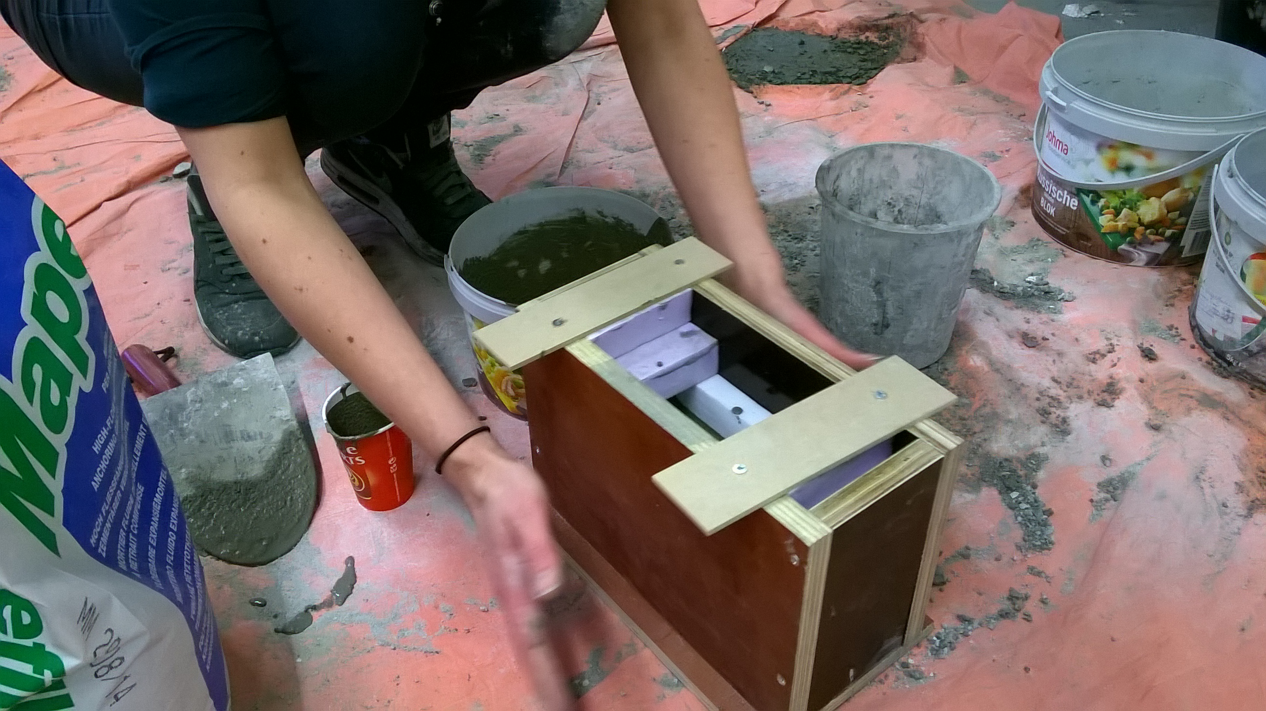
Nadia designed a re-useable moulding technique. To test and show the quality and esthetics she build a 1:7 scale mould and concrete scale model. In the building process laser cutting would be replaced by CNC-milling. The photo’s above show the process of the model: taping the MDF laser cut, building the mould, pouring concrete, covering the mould and the end result.
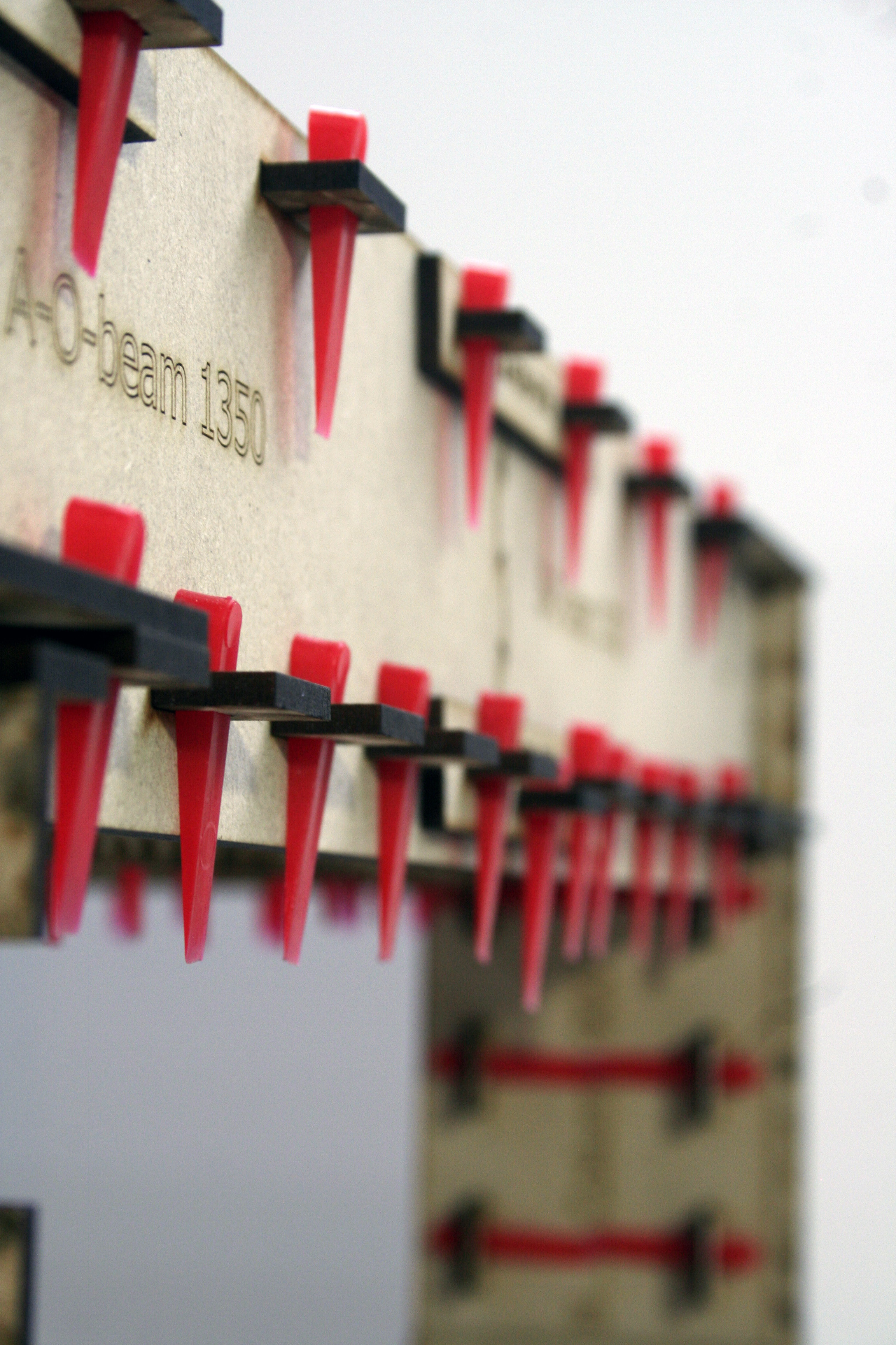
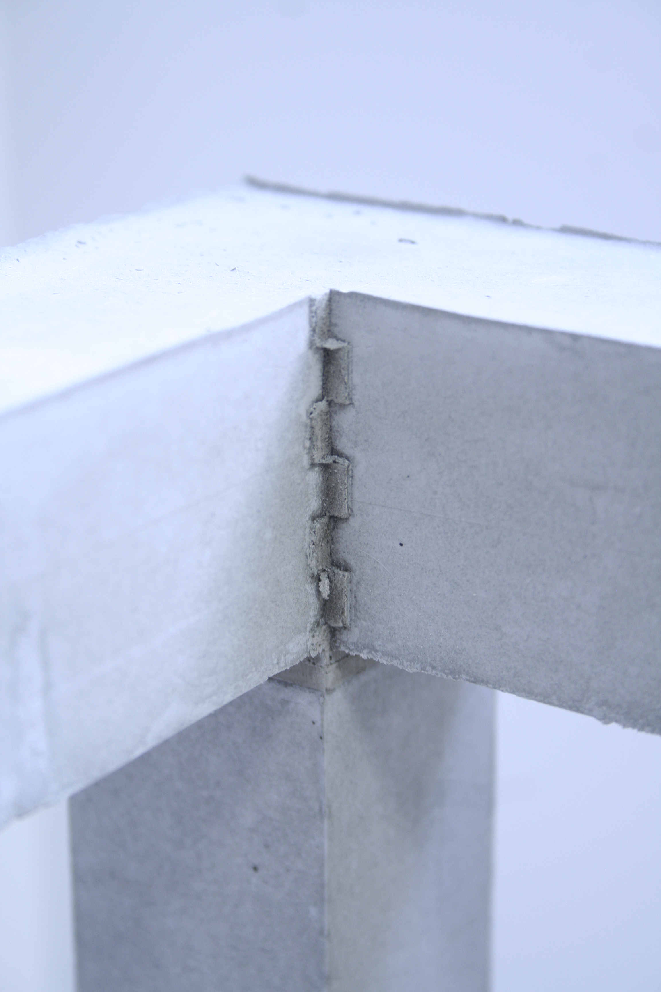
The tile wedges made it possible to simulate wooden wedges on a smaller scale. A bonus is the impression of the seams in the mould visible in the surface of the concrete. Nadia has been nominated for the archiprix and she is competing for the ASN world prize.
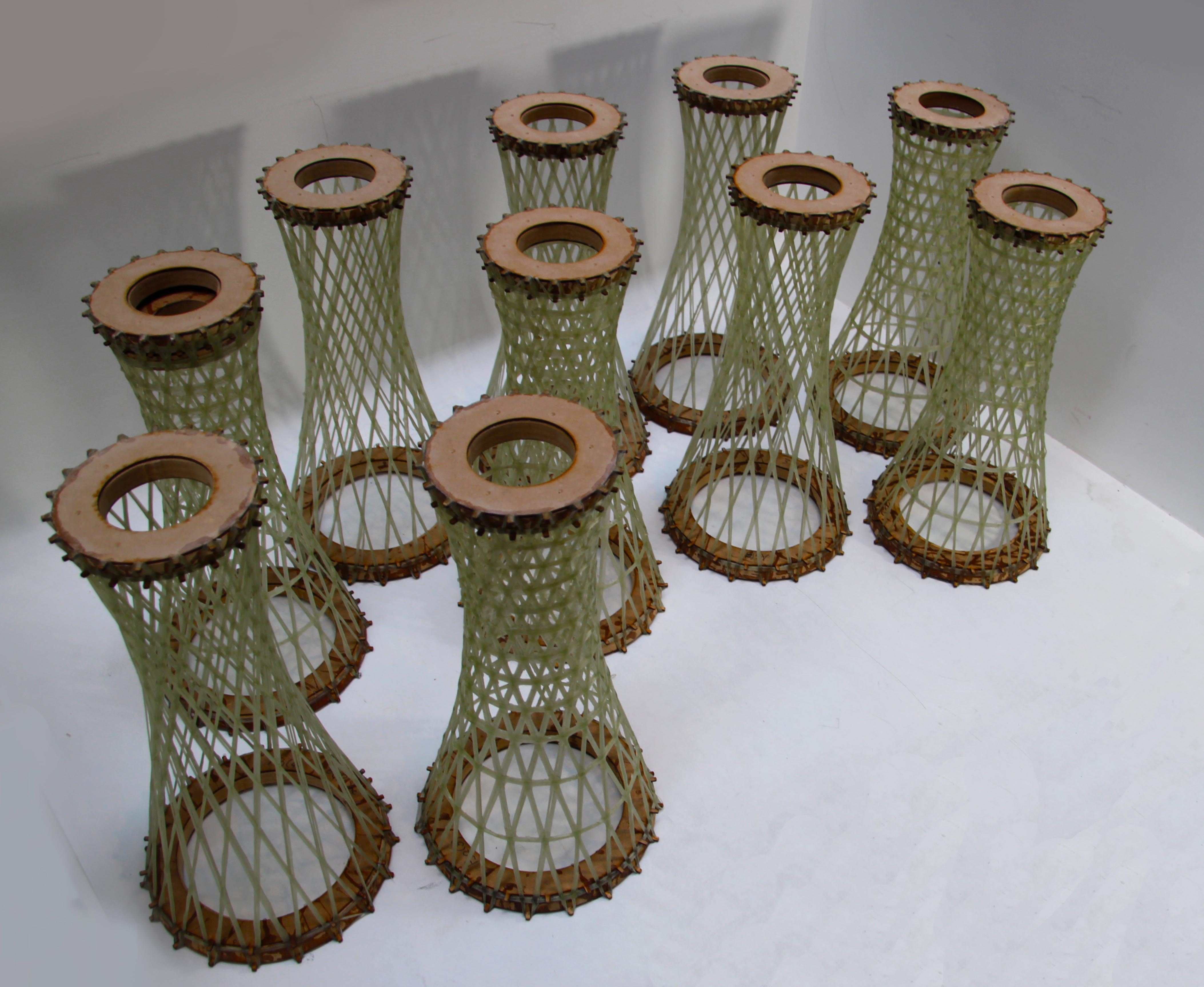
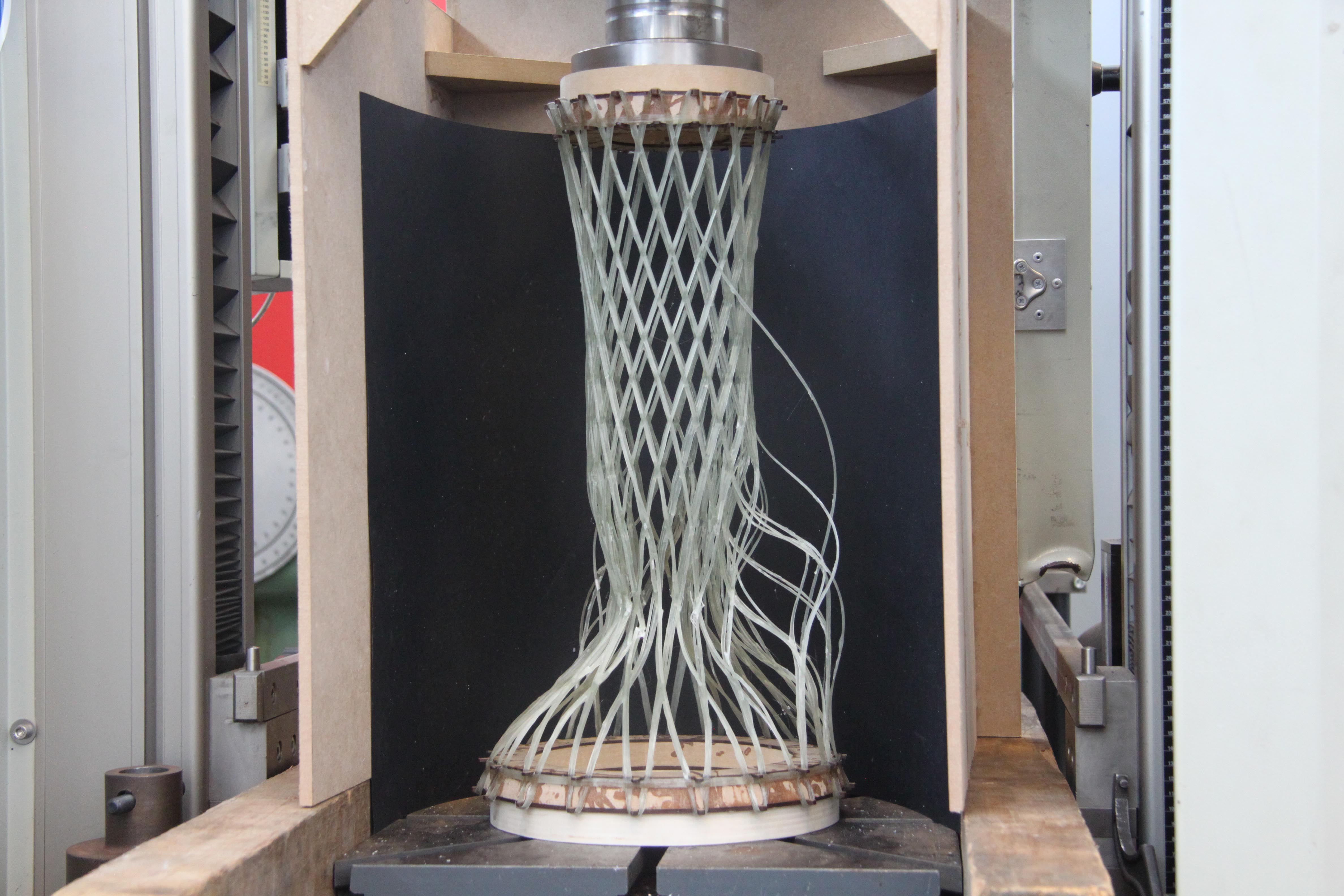
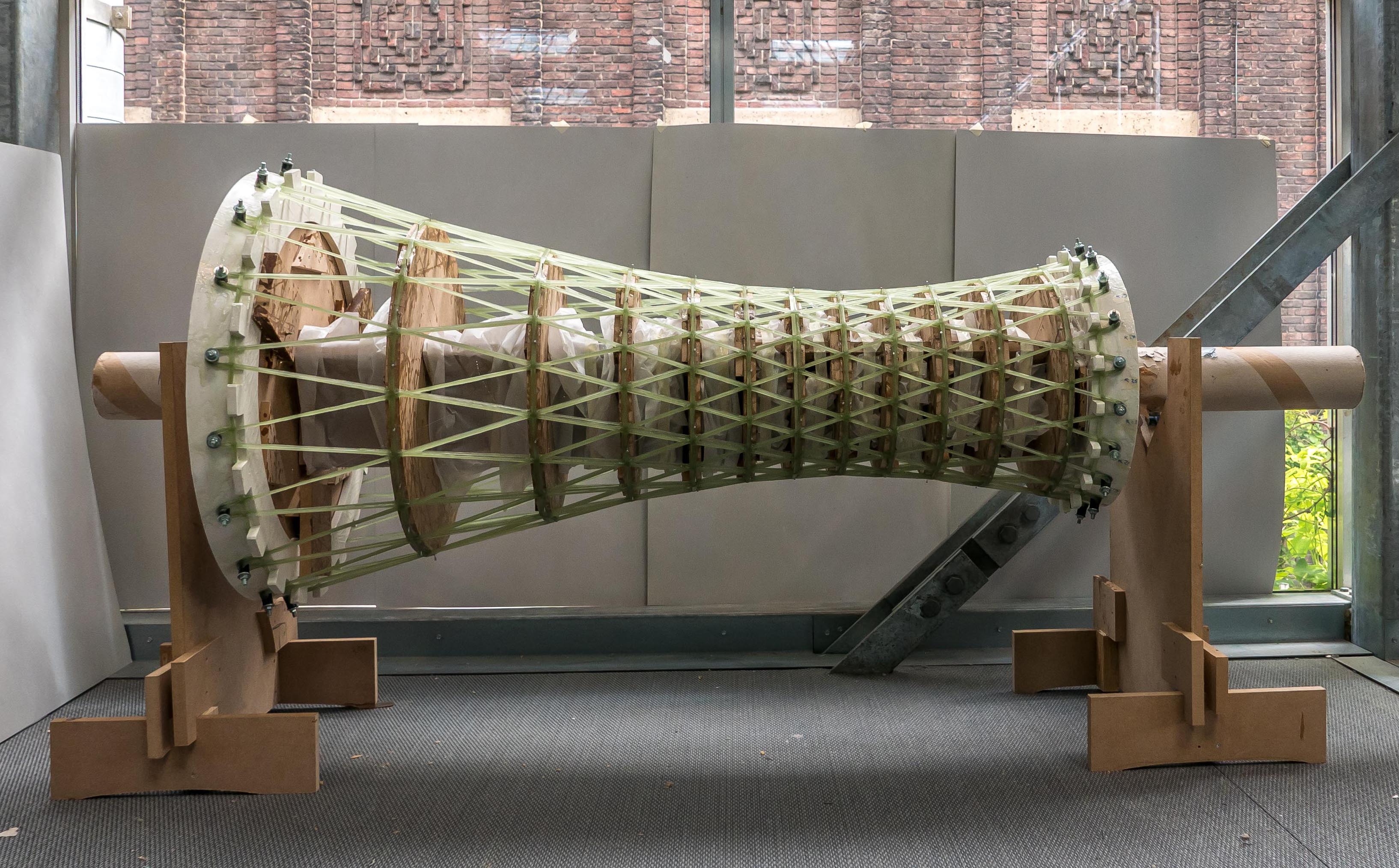
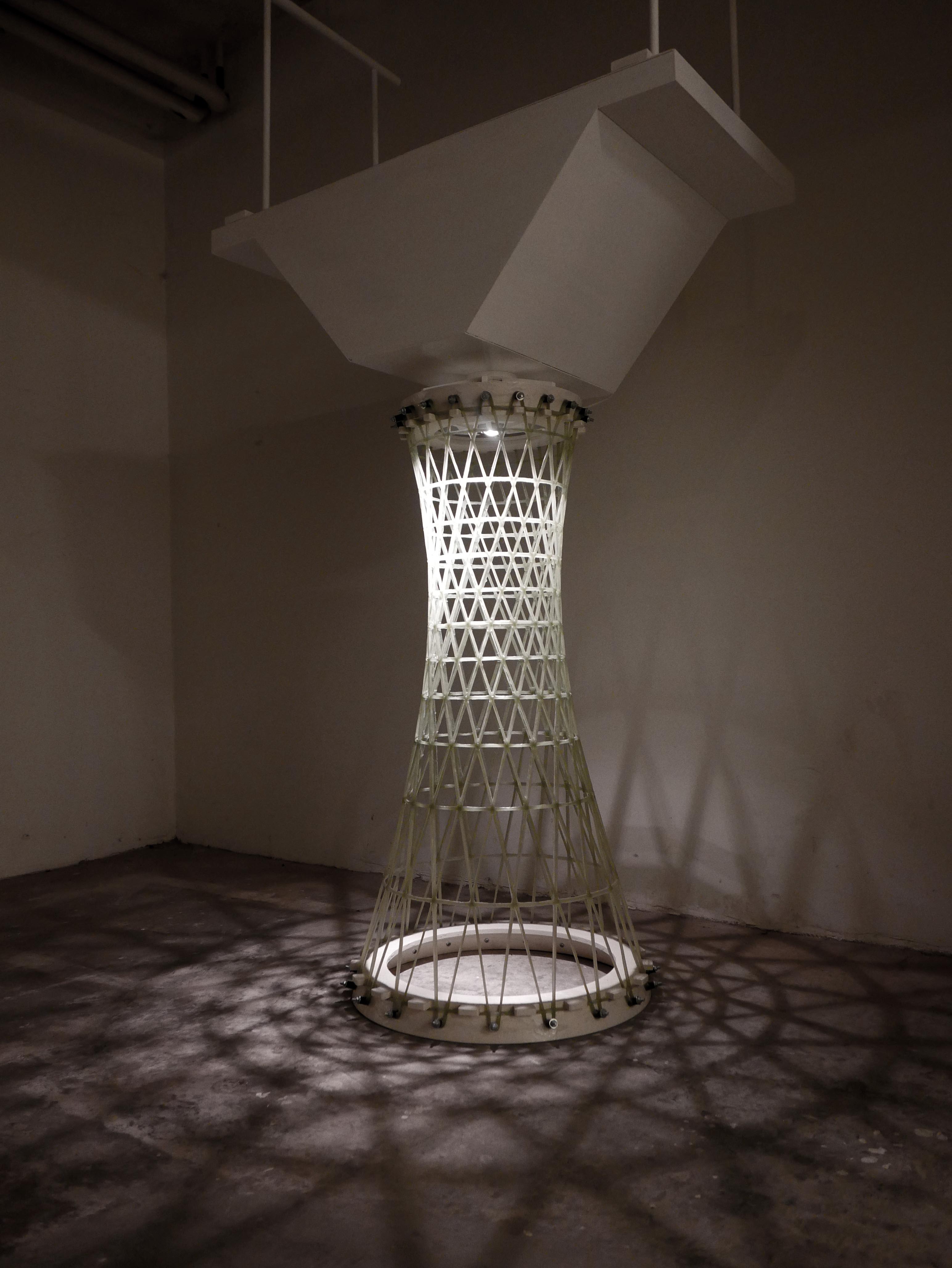
Pierre Mostert’s graduation project focusses on the pillar for a pedestrian bridge. A glass fiber wire, pulled through resin, is wounded around a rotating mould. The weight test shows the small columns could hold about 1000 kg. Lots of hours of hard work and discussions and tests resulted in an impressive and realistic design.
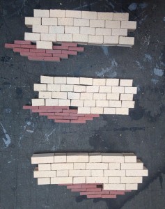
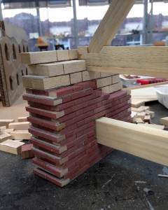
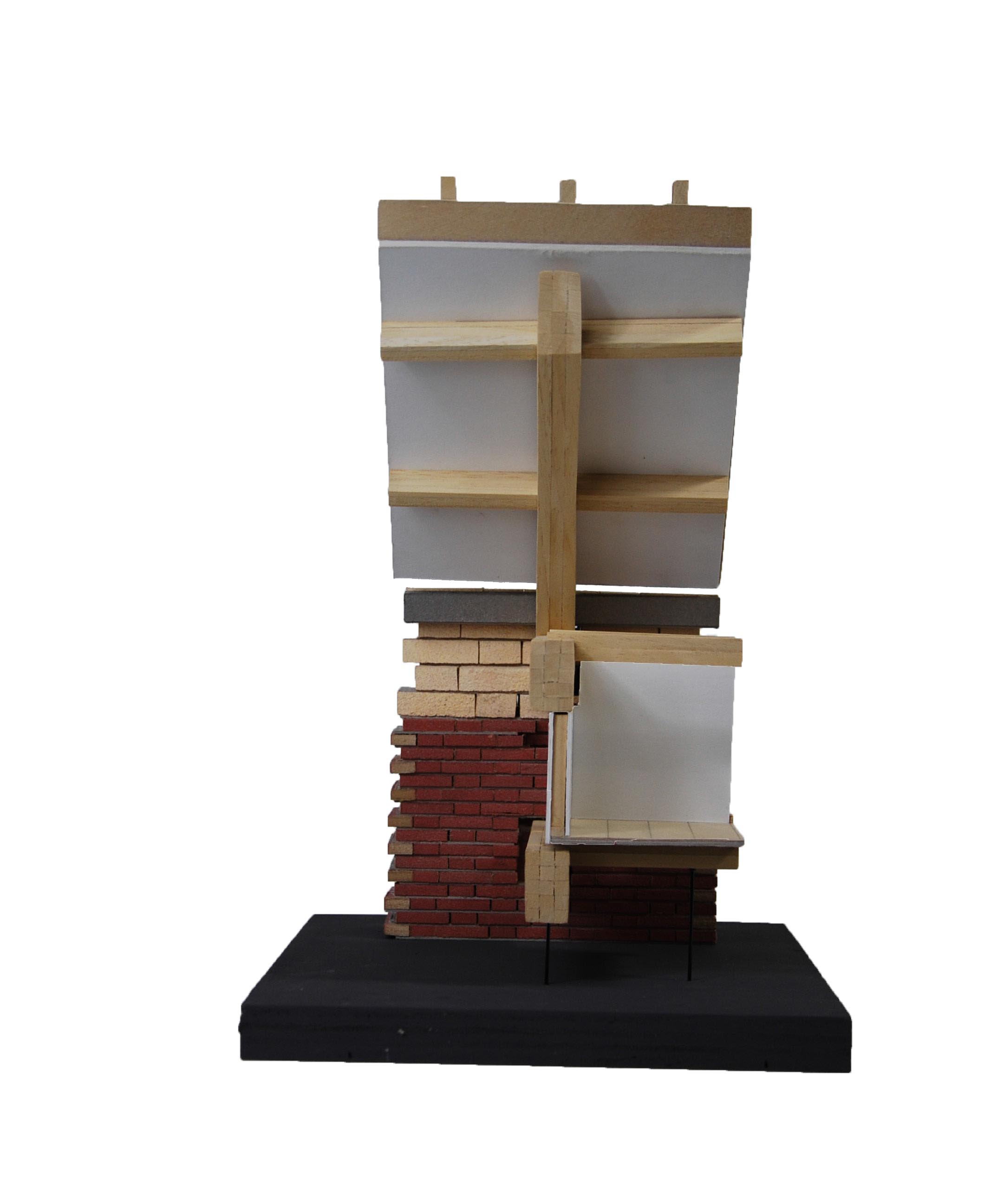
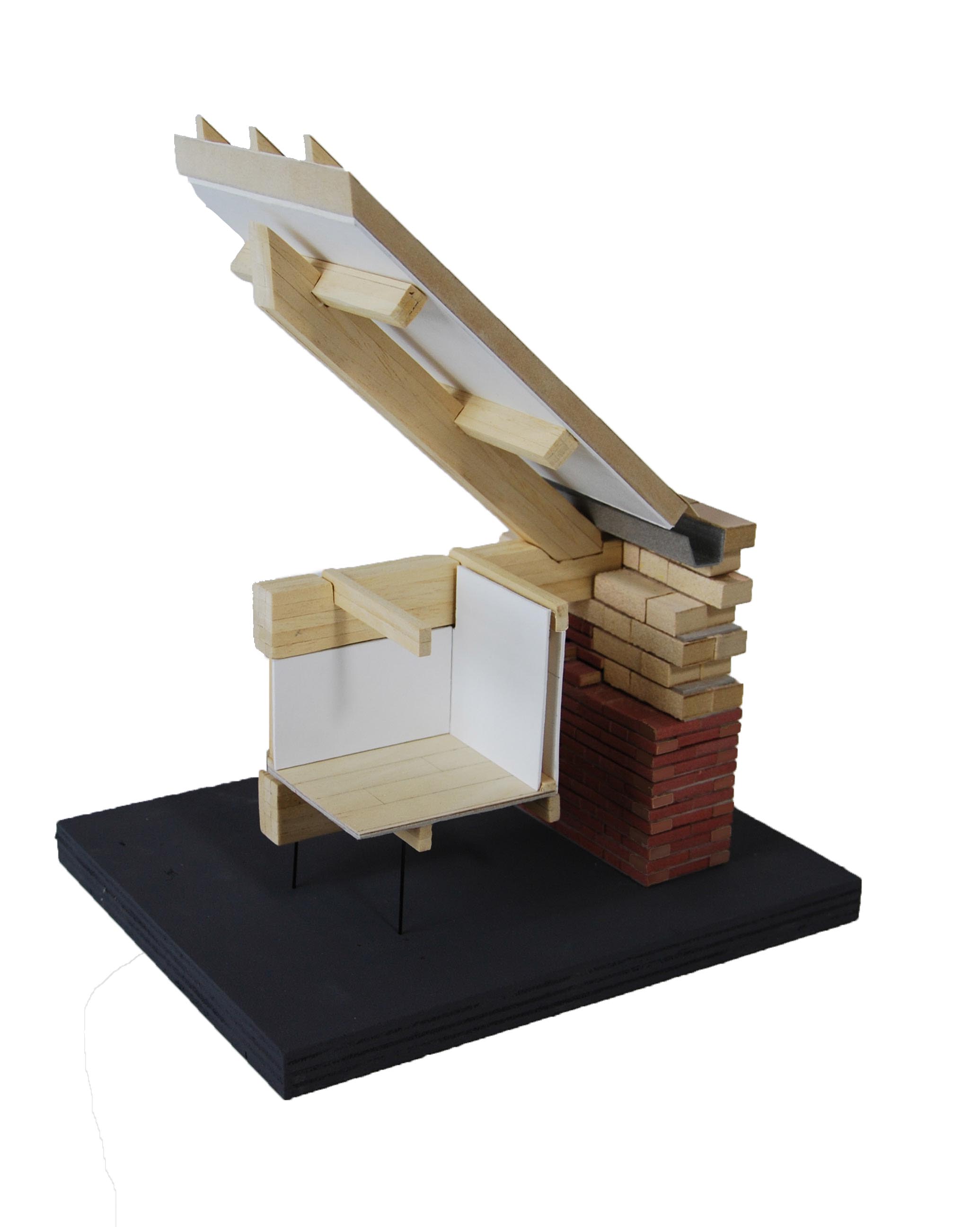
Aukje Schukken did The Delta Shelter project (AR0211). To be able to show the detail how the brick wall meets the roof structure she made a 1:20 model. She started with stripes of MDF, painted these in the right color. By using spray paint the different colors of the bricks can be shown, after the base color has been applied by hand. After painting the long sides she cut them into the right size. Pieces of cardboard are used as seams between the bricks. She shows the building process can be figured without building a 1:1 scaled wall.
Clara Jansen uses resin to show the water surface in her graduation model. A plate of plywood is used as a base because it’s stiffness and surface qualities. The edges have been sealed by pieces of MDF, which are treated to enable a smooth detachment. The resin has been colored by pigment powder to create the right contrast and to fit in the color scheme of the model.
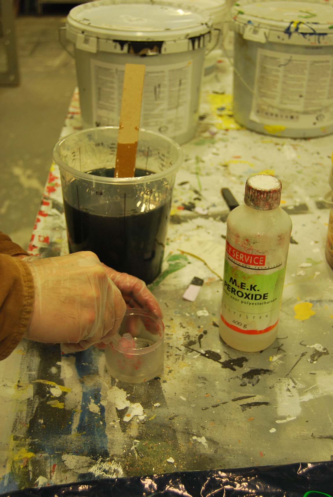
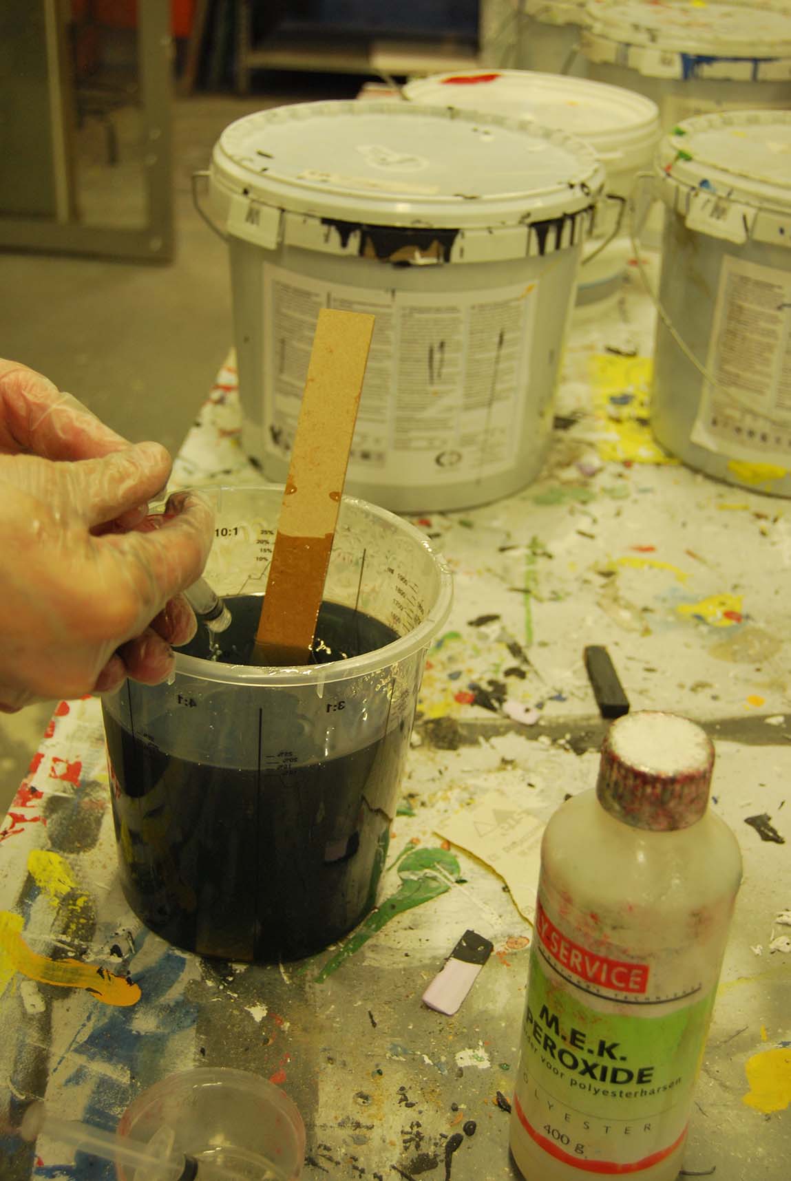
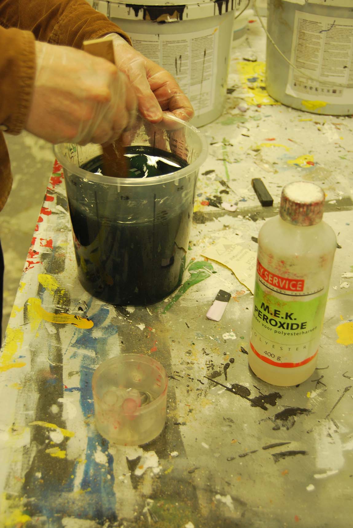
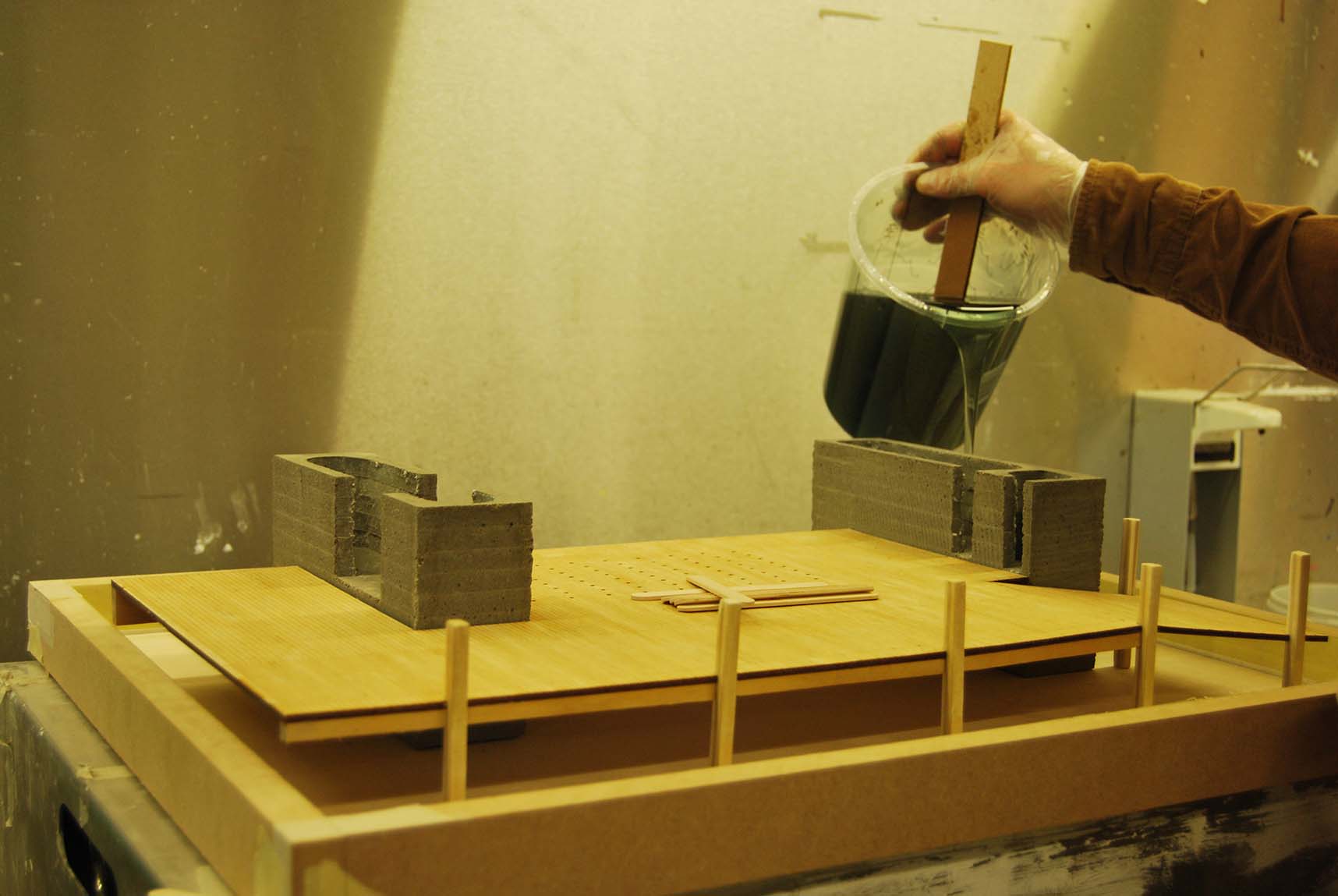
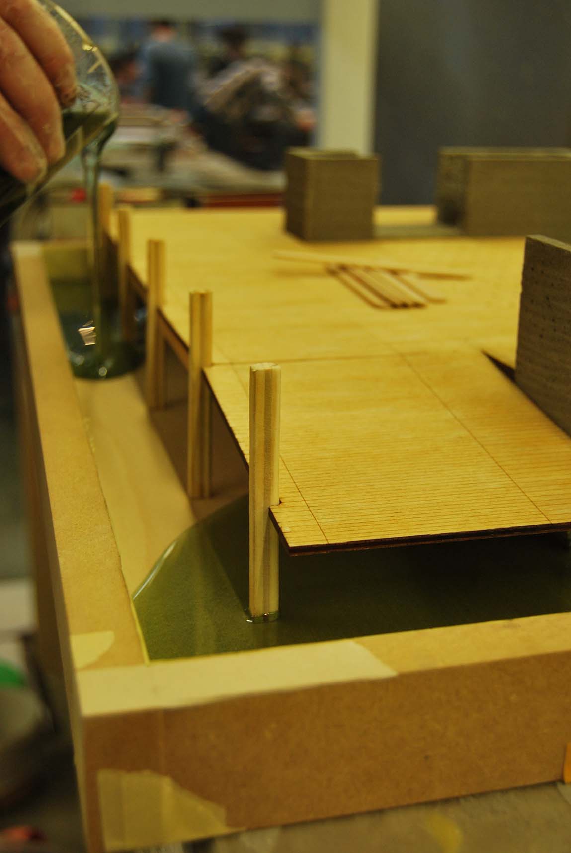
Before pouring the volume of the resin has been determined. MEK harder is added to the resin in the right percentage and the resin mixture is being mixed by hand. This is only possible if the right safety regulations are regarded, don’t try this at home! The resin is being poured carefully and the model has to rest for a weekend.
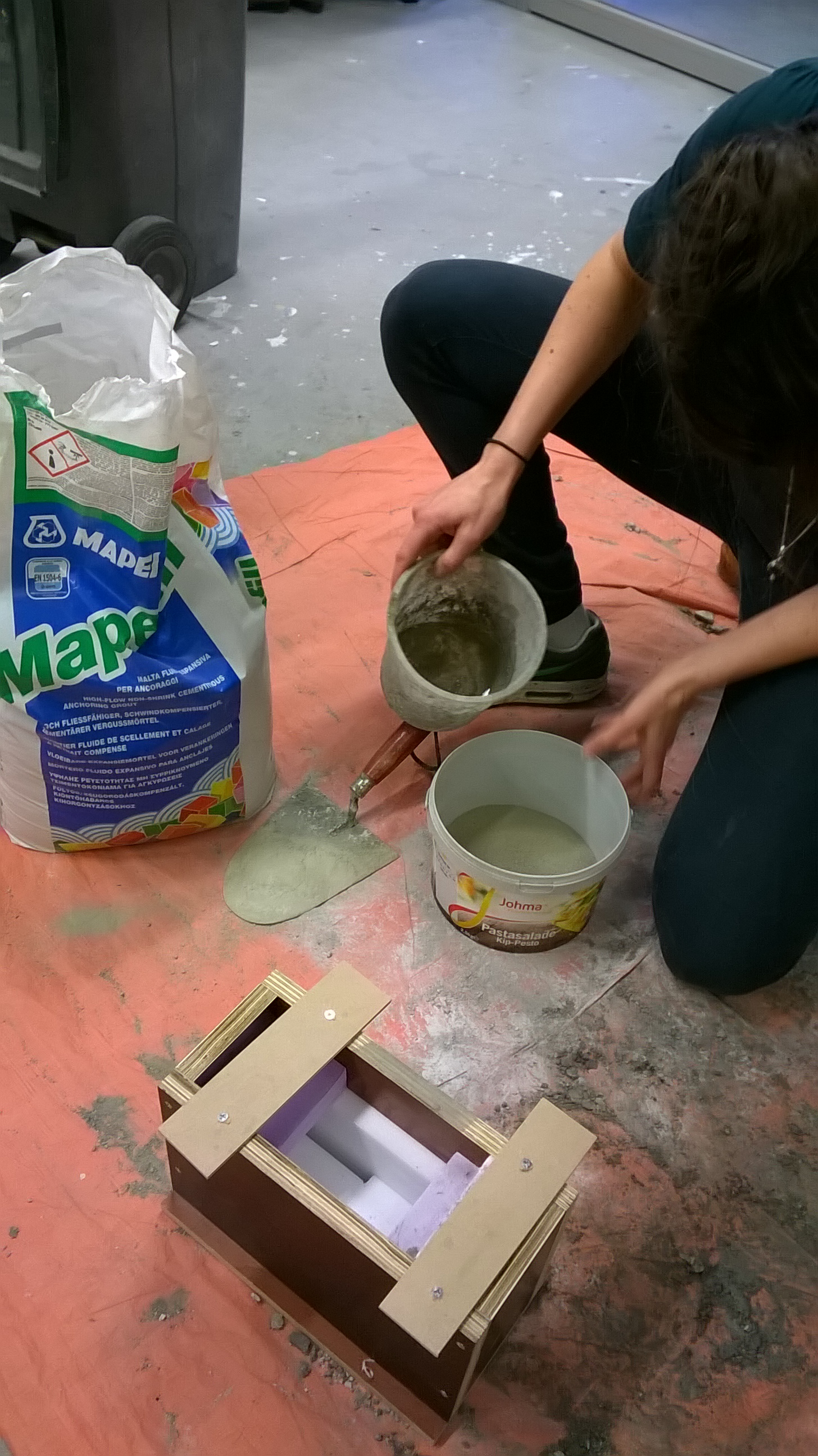
Clara Jansen uses concrete in a repeated casting process. The wooden box can be reused, the foam blocks inside are different for every block. Before casting concrete it could help to read the following basic information:
• Mould making.
The mould must be watertight. This can be ensured by precise tailoring of the components from which the mold is made. If this is not the case any seams can be sealed with acrylic kit.
The shape must be solvable. A releasable form is constructed from wide to narrow and has no projections or protrusions. Any locked parts must be filled with foam. If this is done with a different material, the unloading will be prevented due to shrinkage. It is important which material is chosen for the construction of the mold. The materials that work best are plywood, vivak, EPS foam sheet and silicone rubber. When plywood and foam plates are used, the inside of the mold needs to be treated with oil.
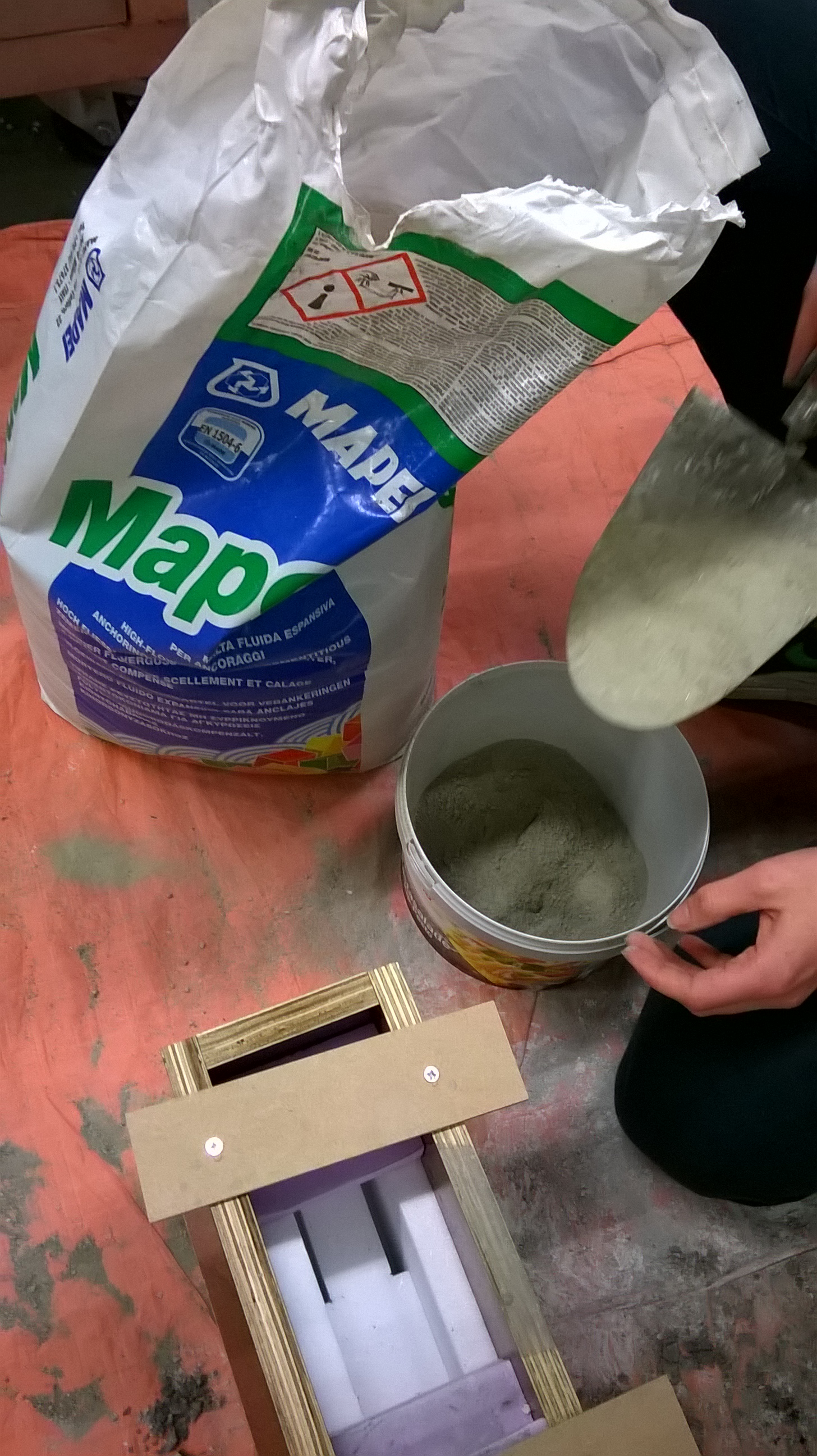
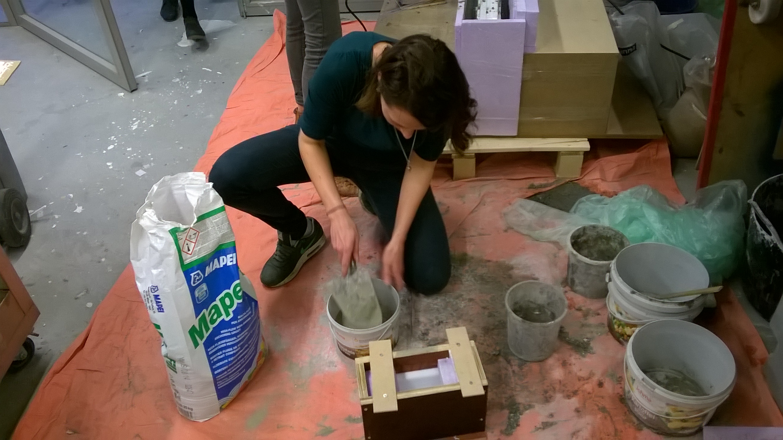
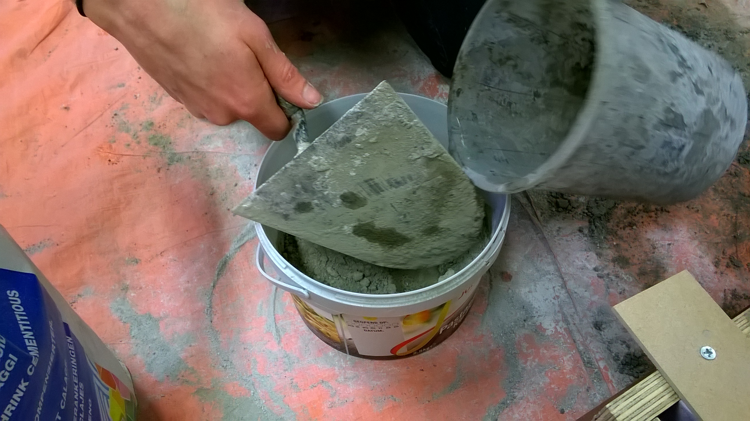
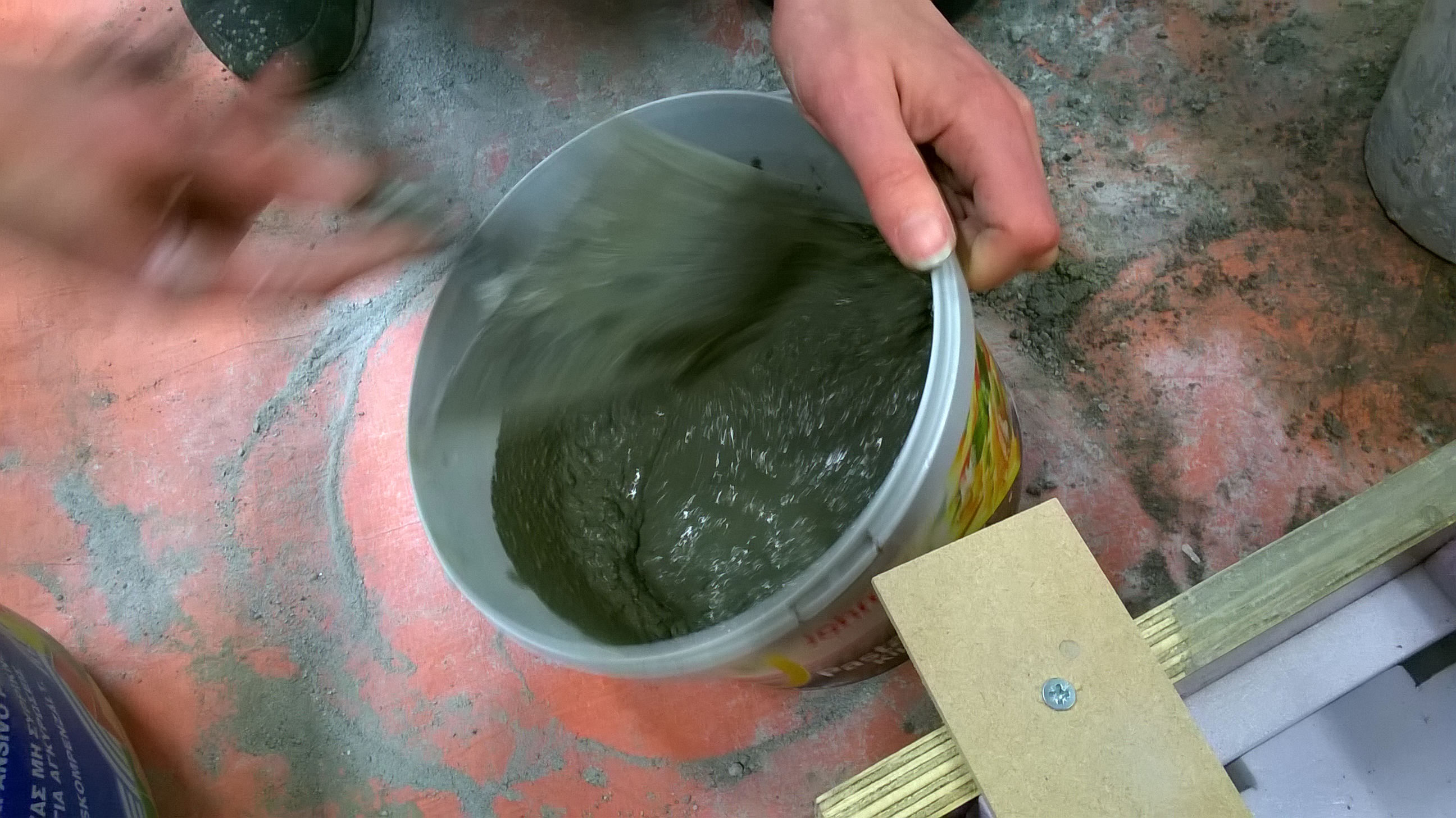
• Concrete mixing.
Before the concrete is mixed the volume must be determined. The solid particles can be measured in a bucket or a tub. Then water can be added. The amount of water must in the end be about 1:4. It is advisable to add it into parts while mixing. If the substance changes from solid to liquid, there is just enough water.
• Composition.
Normal concrete consists of: 1 part cement, 2 parts of sand, 3 parts of stones and 1 part water. The concrete that we usually have in stock misses the stones, instead some gravel or fibers have been added.
• Casting.
During the casting of the concrete a large opening is needed. When the mold is filled, shake slightly to get rid of the bubbles. A compact size causes a high temperature. It’s recommended to cover the mould with foil for one day to prevent the concrete from drying out.
• Unloading.
Before it can be unloaded it’s recommended to wait for at least two days. The unloading takes some strength sometimes, depending on the construction of the mold. Try to take this into account in advance so that the cast does not break when unloading.
• Tools.
There are buckets, a trowel and a mixer available on the faculty. Please clean all tools by rinsing with water after using it. Do not pour the water into the sink, the concrete must settle in the bucket first.
In this case the building process is being imitated by the building process of the model. This is a way of learning about material quality and creating images to show the ambiance at the same time.