Category Archives: Projects

Temple of the Natural Delights; constructing abstract seduction

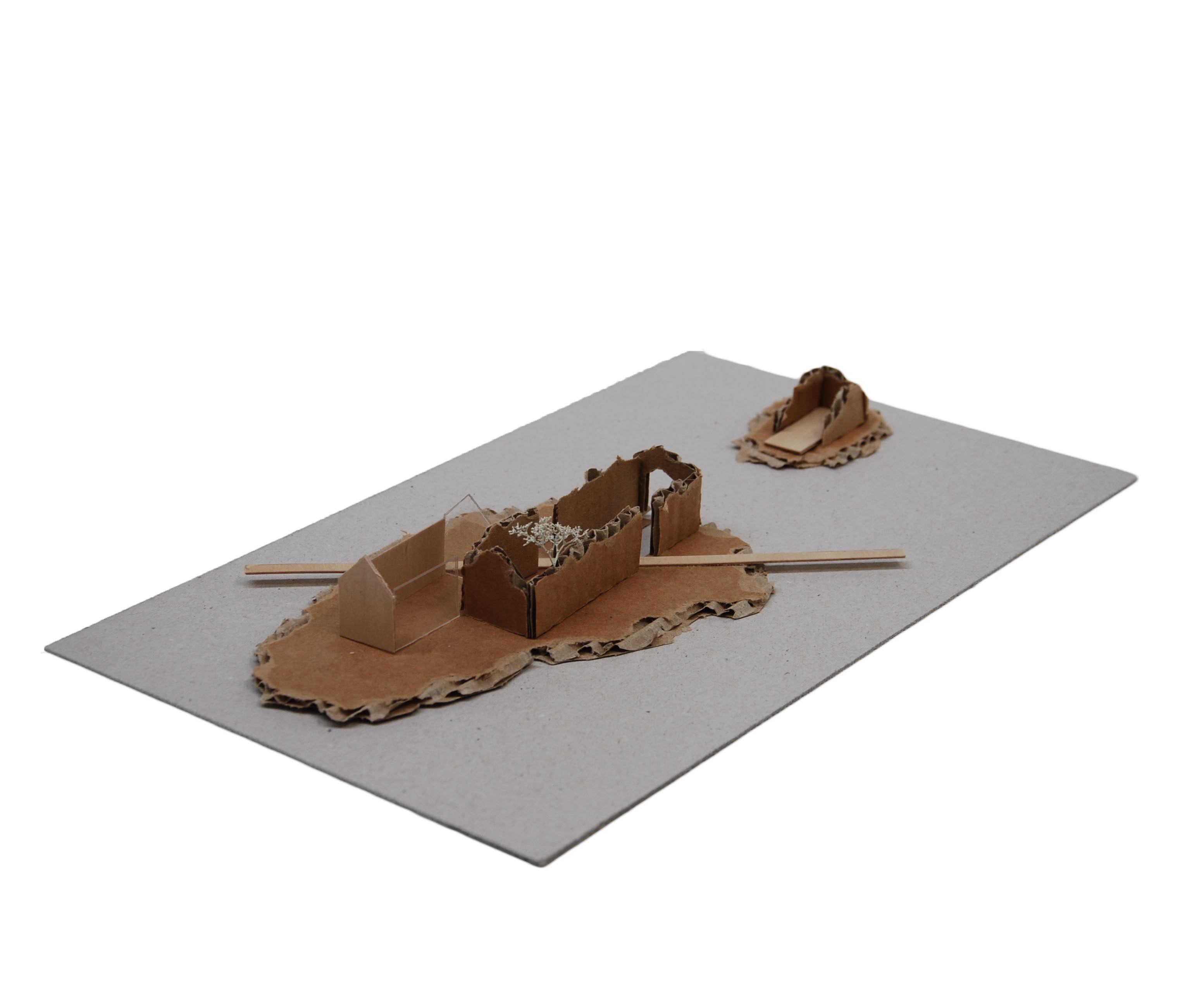
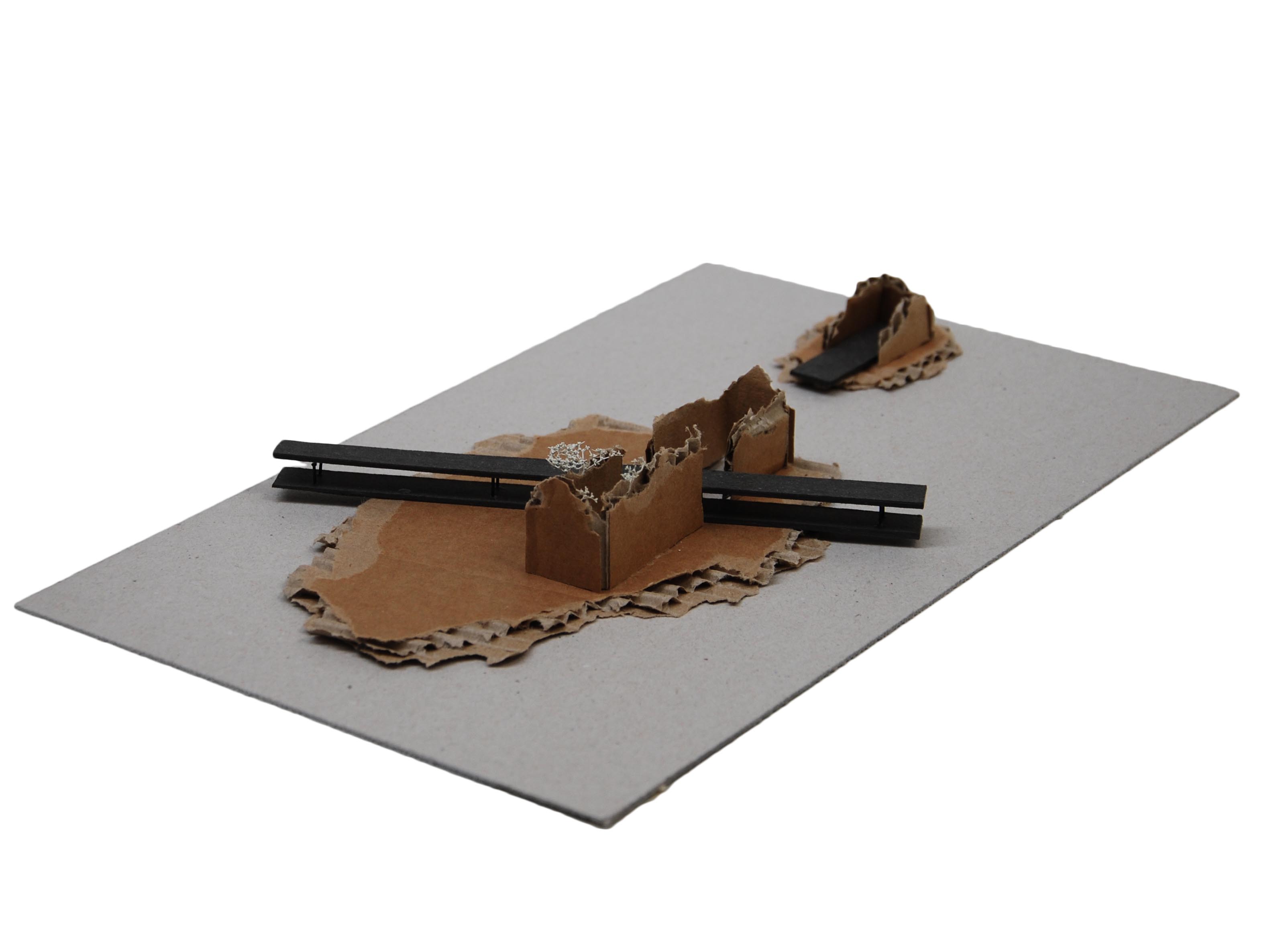
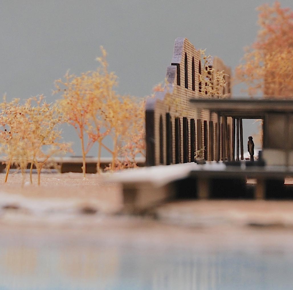
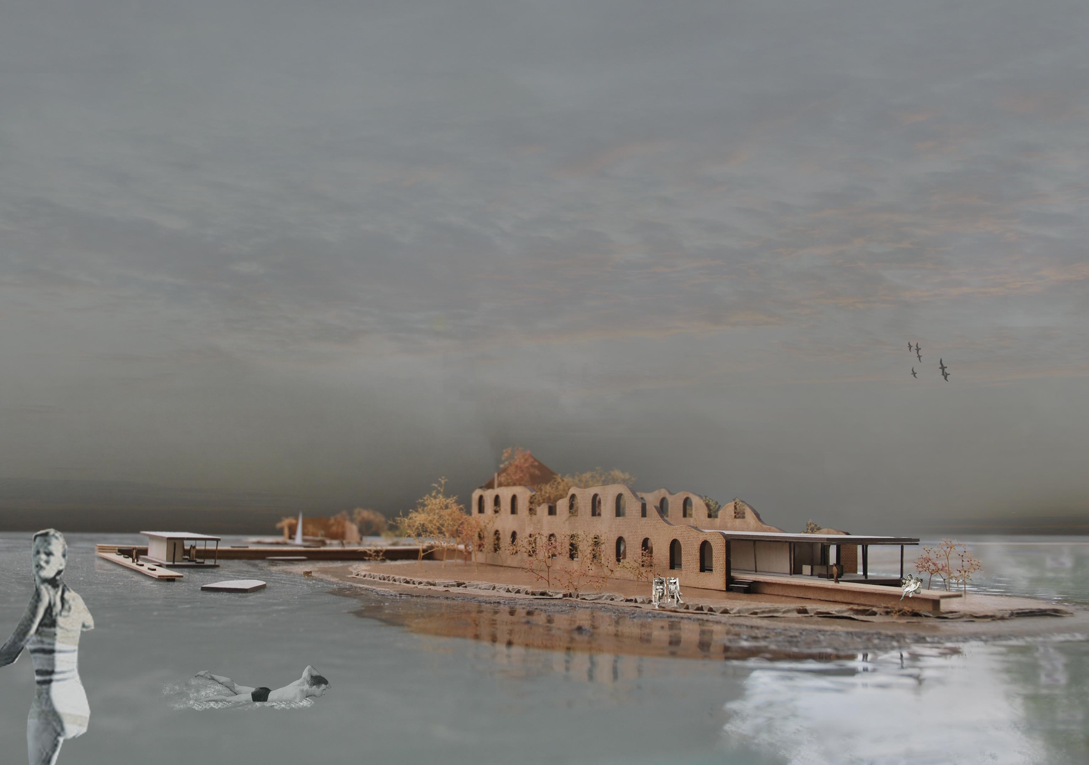
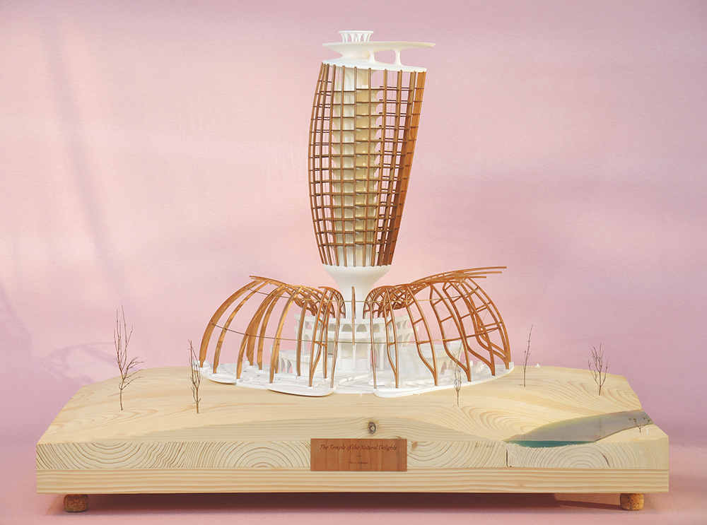
The aim of the project is to accelerate the transition towards a longer lasting society. A new narrative is advocated to engender the desire for a sustainable future. Within this new narrative, temples are situated in the great metropolises of the world to propagate ecological thinking. The aesthetic and architectonic expressions throughout the public and private realms embody an ethic that endeavours to seduce one to live this new lifestyle. The building and its context are an autarkic unity; designed to satisfy the user’s needs through the use of natural principles in synergy with the ecosystem. Building physics, construction and material considerations form the basis of the generic design. The building materials are recycled and absorb greenhouse gases, thus counteract climate change. Its archetype is to be adjusted depending on the geo-specific context and climate of the proposed temple, creating a network of true localised altars to the Natural Delights.

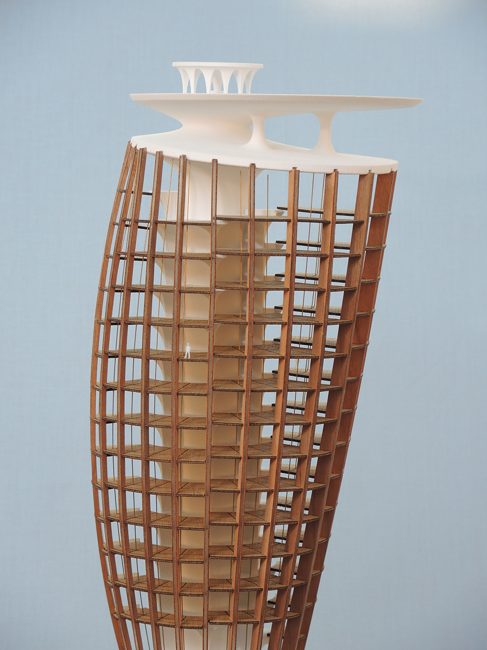
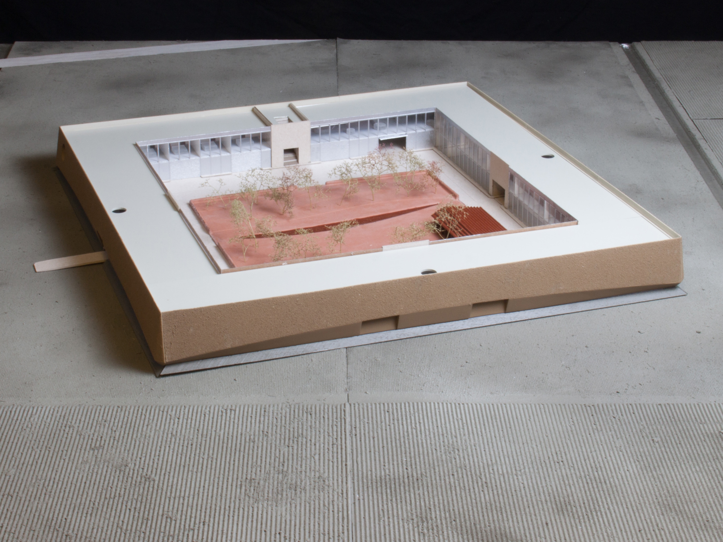
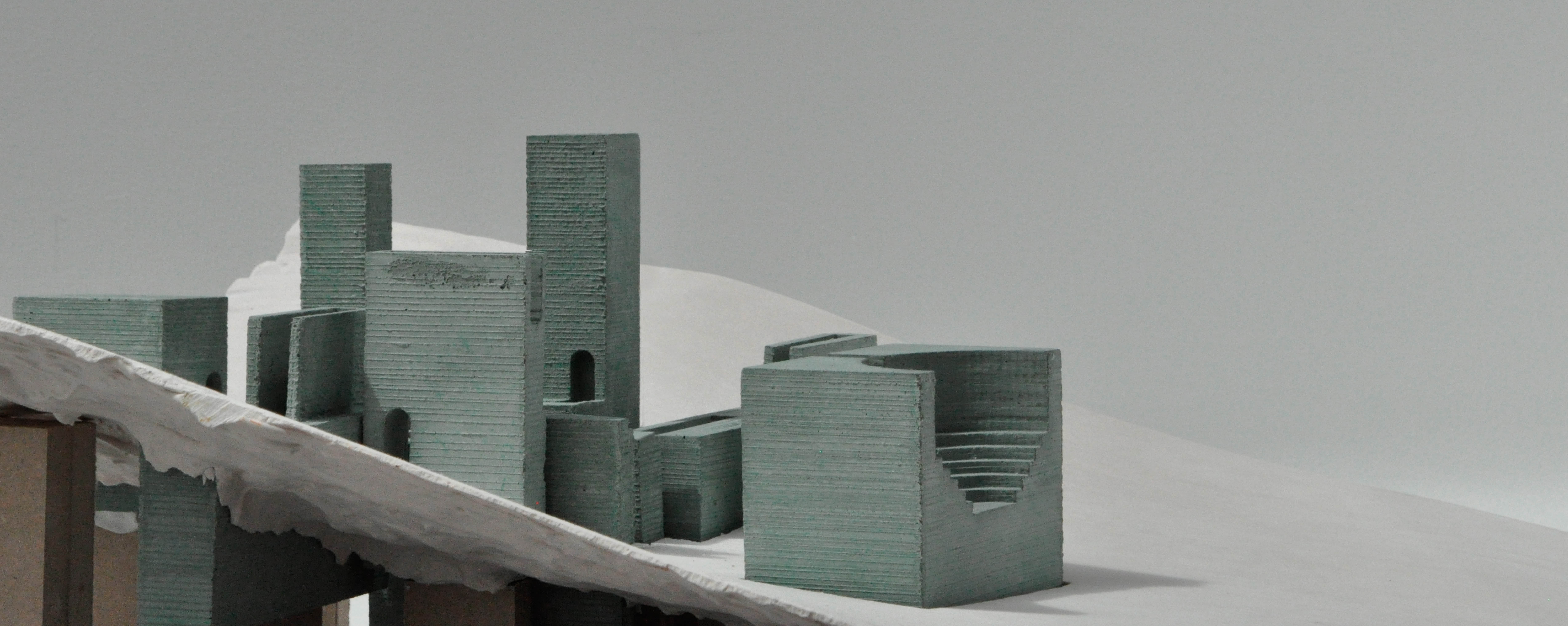
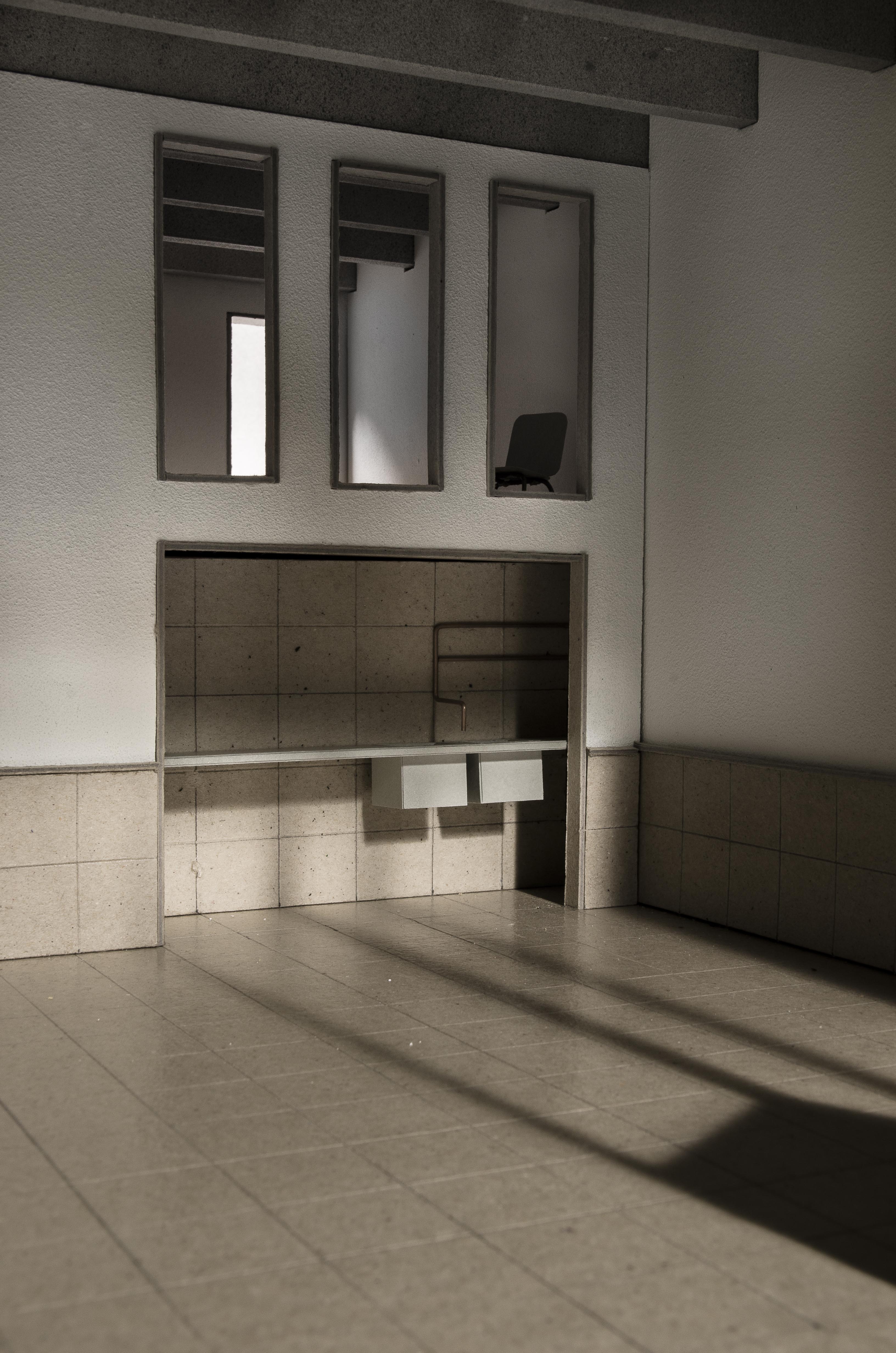
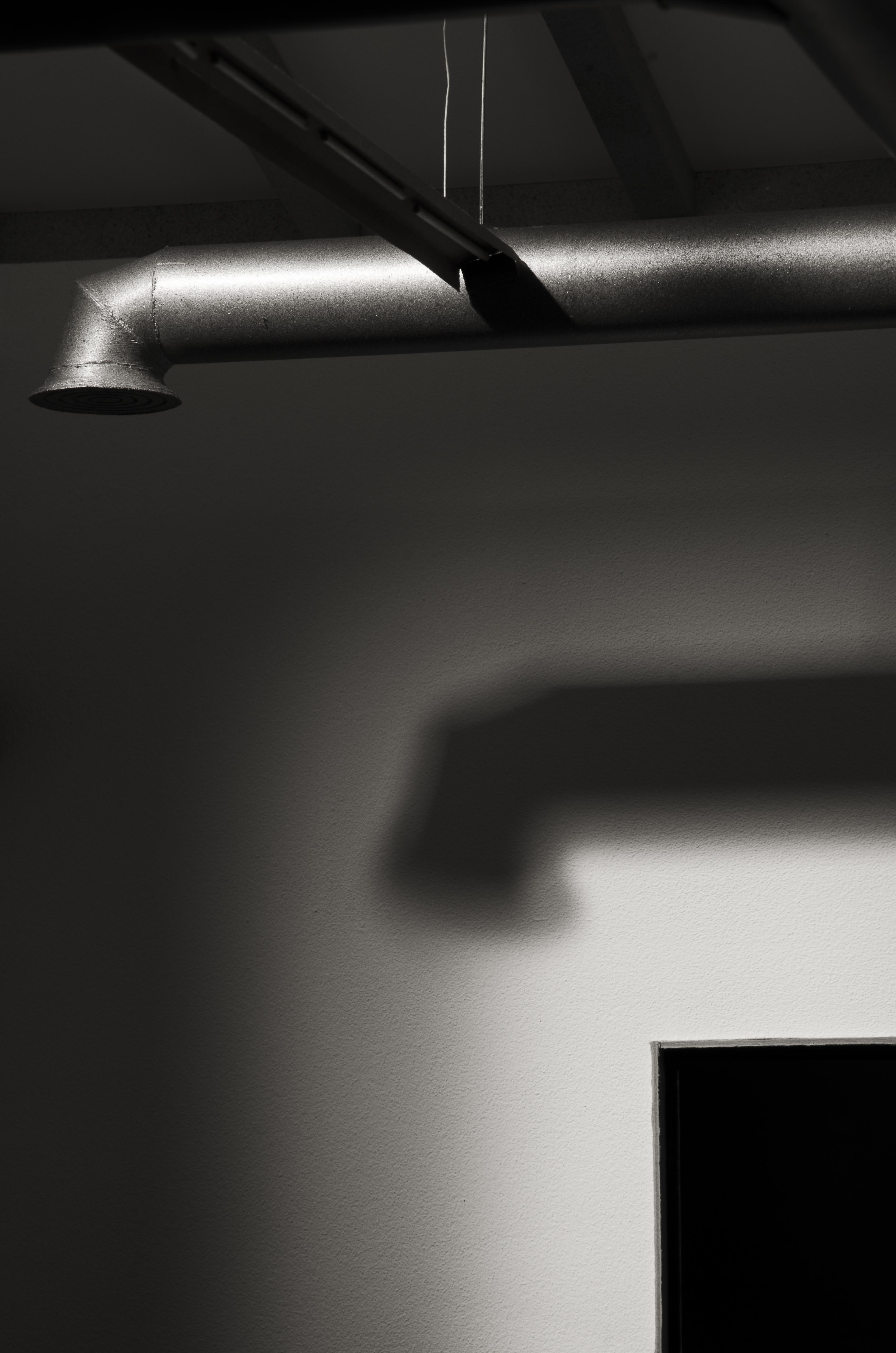
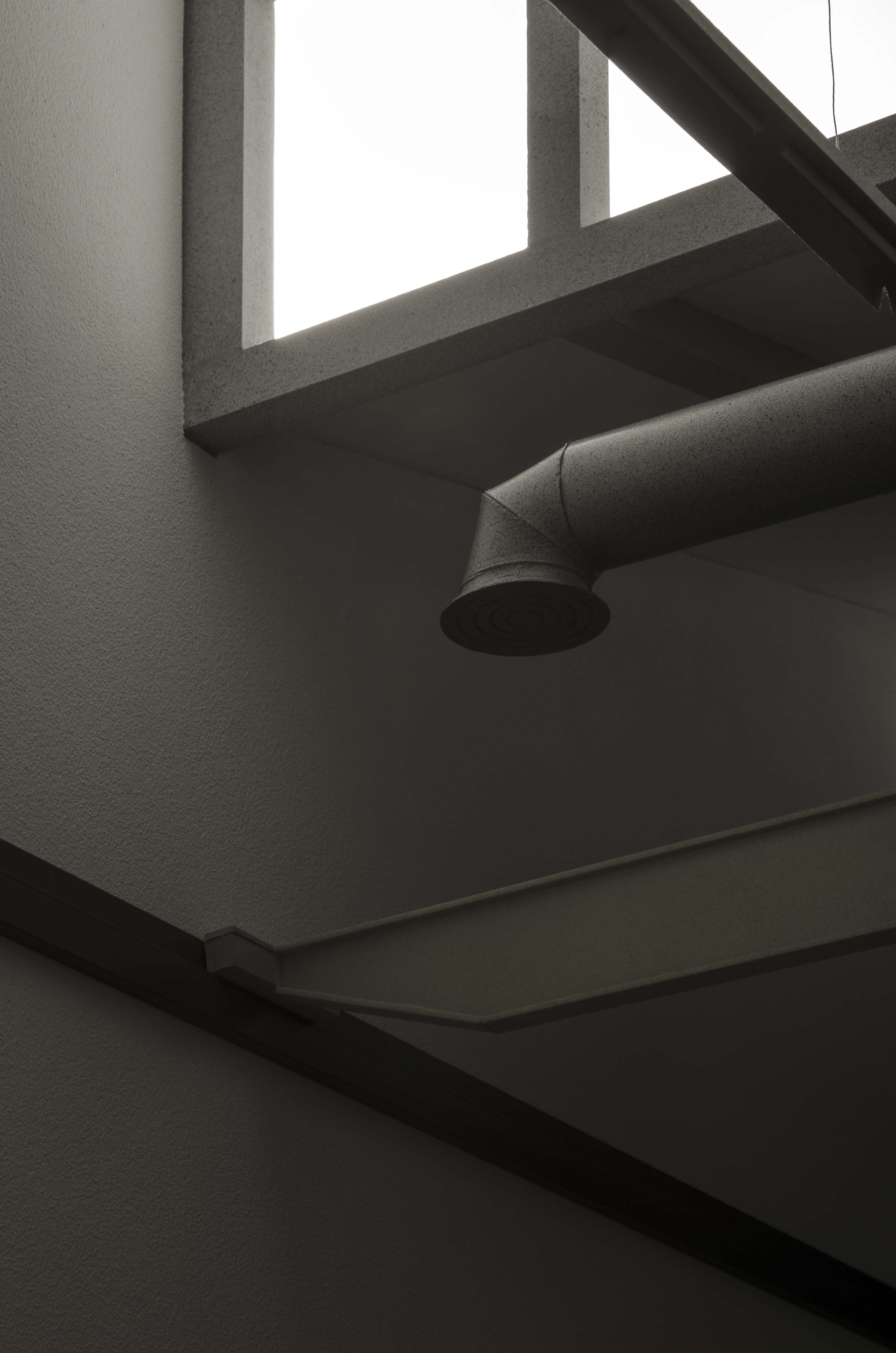
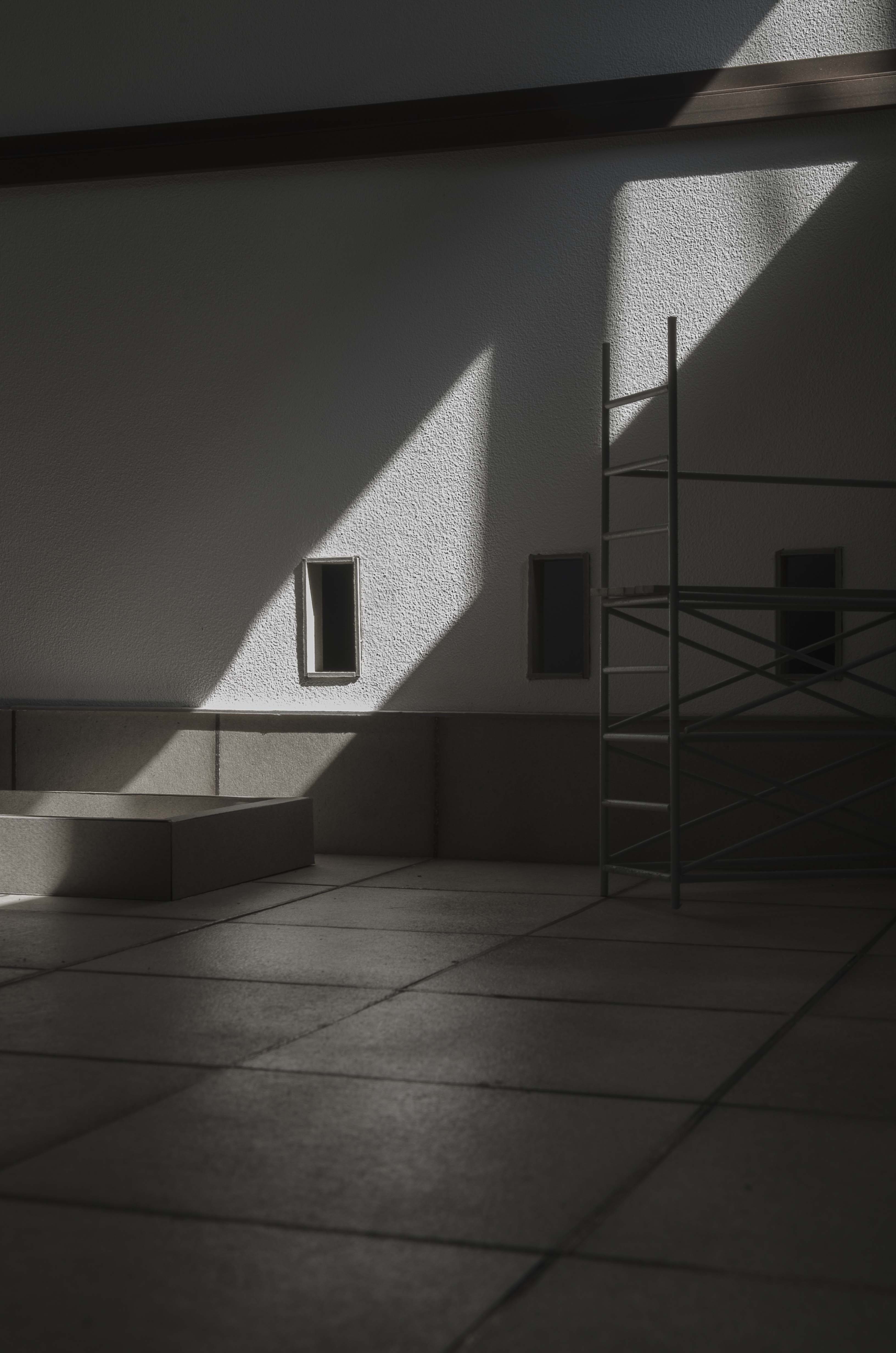
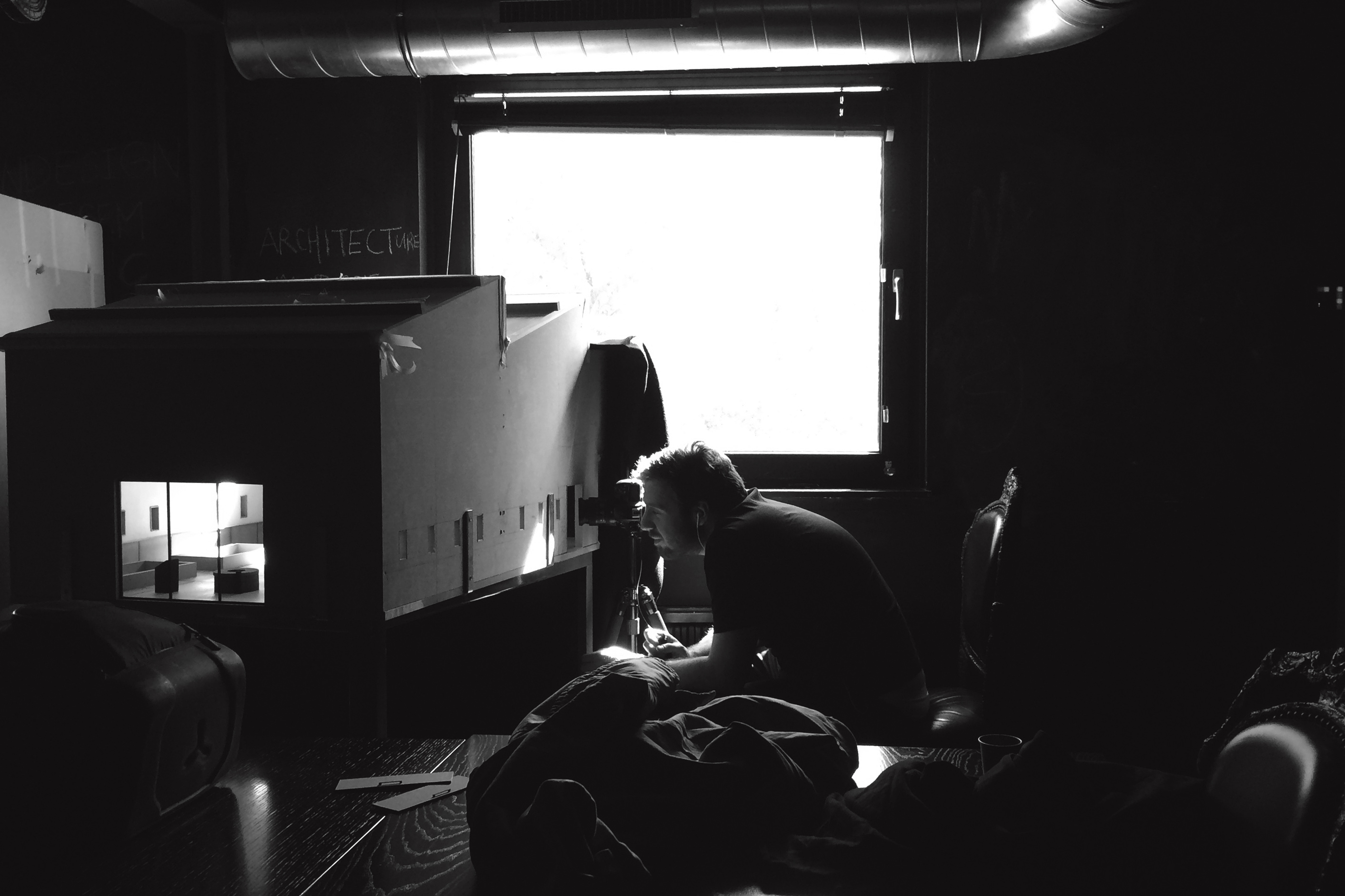
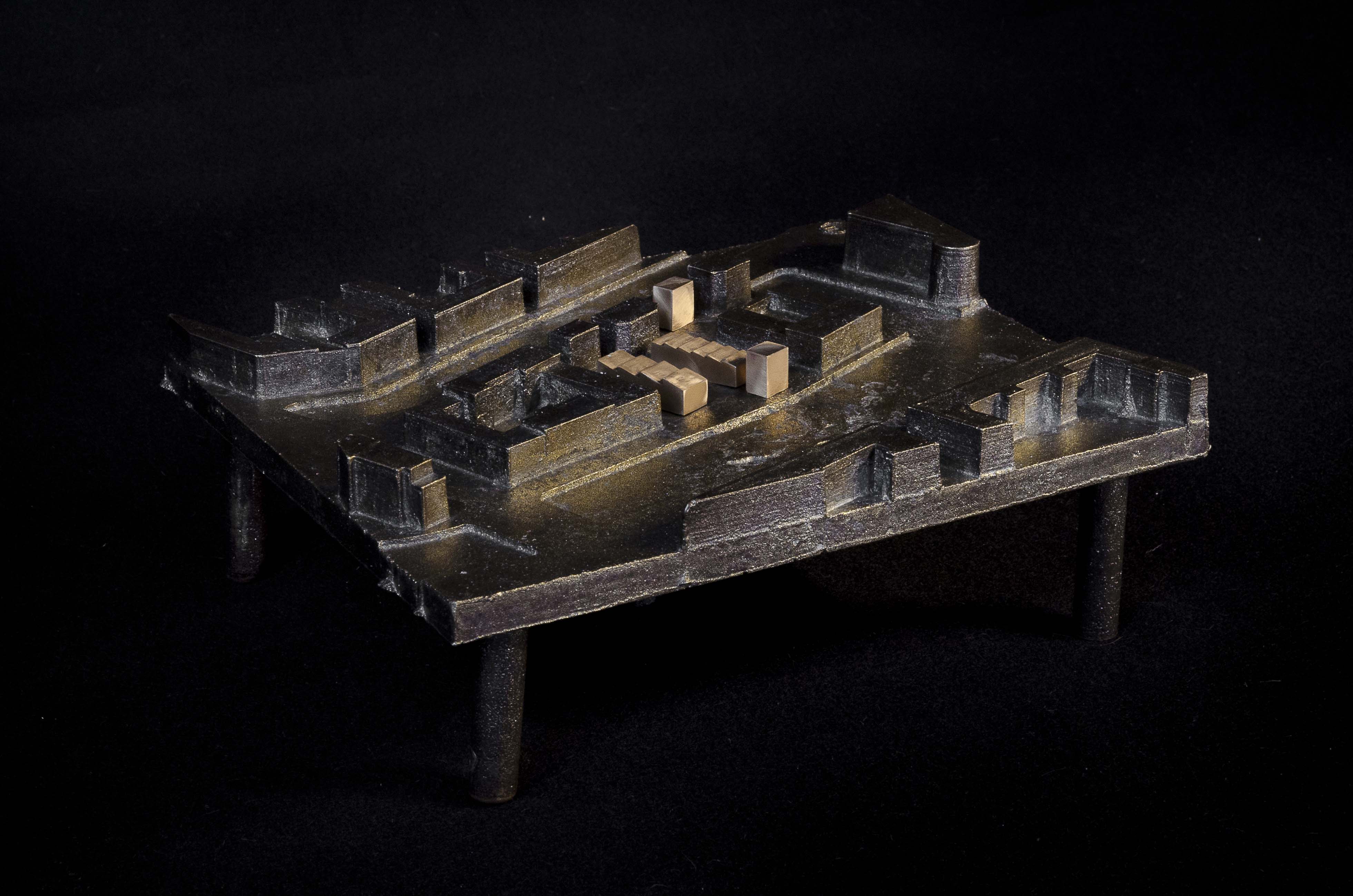
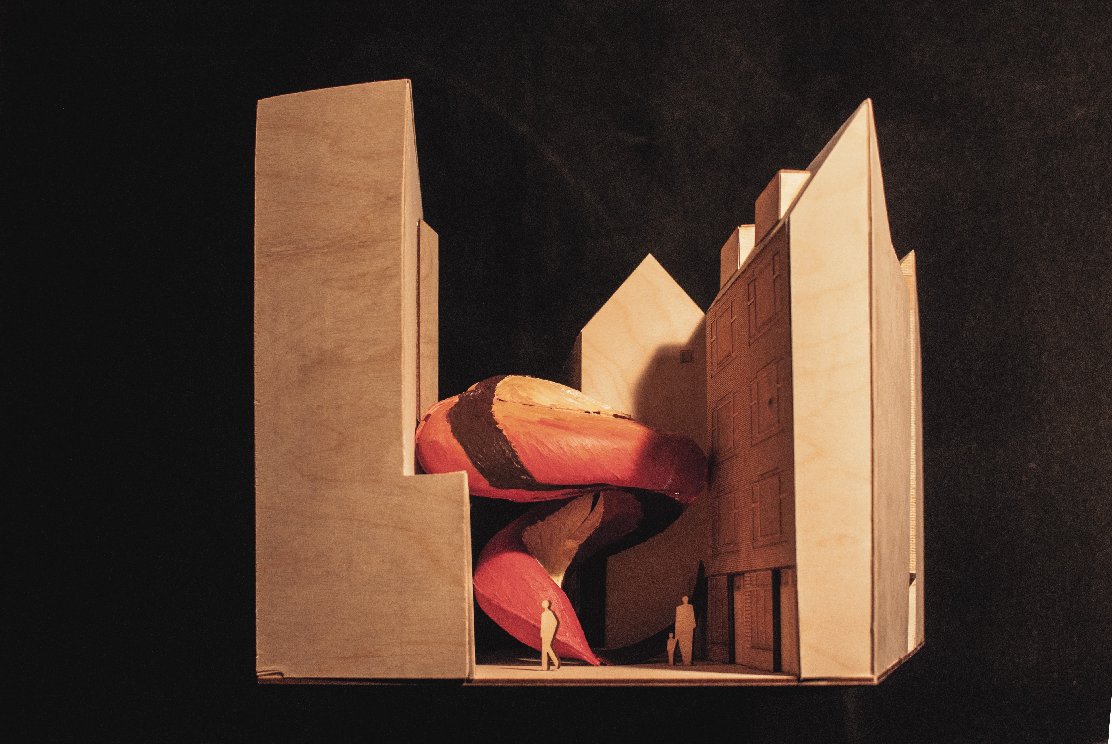
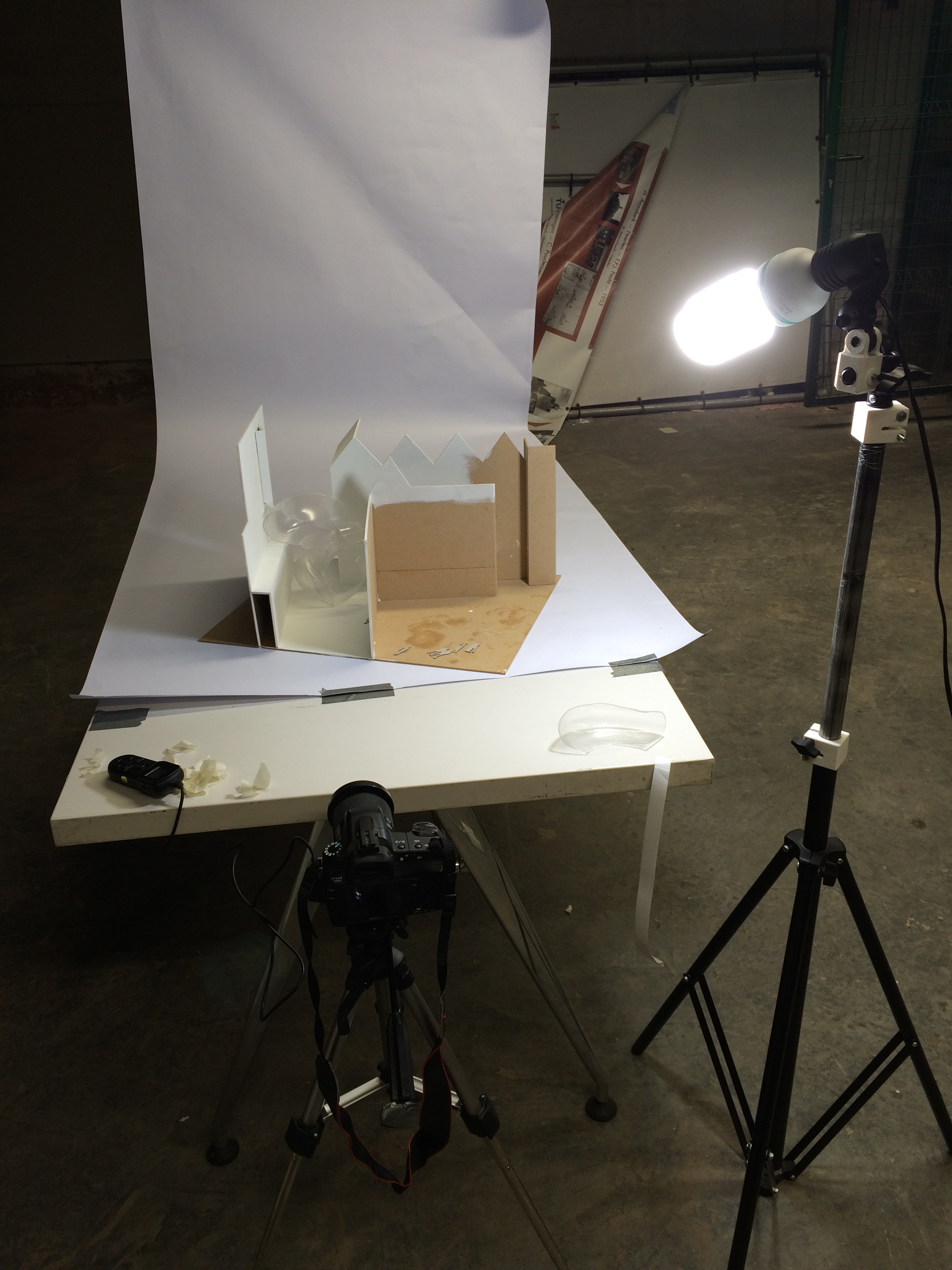
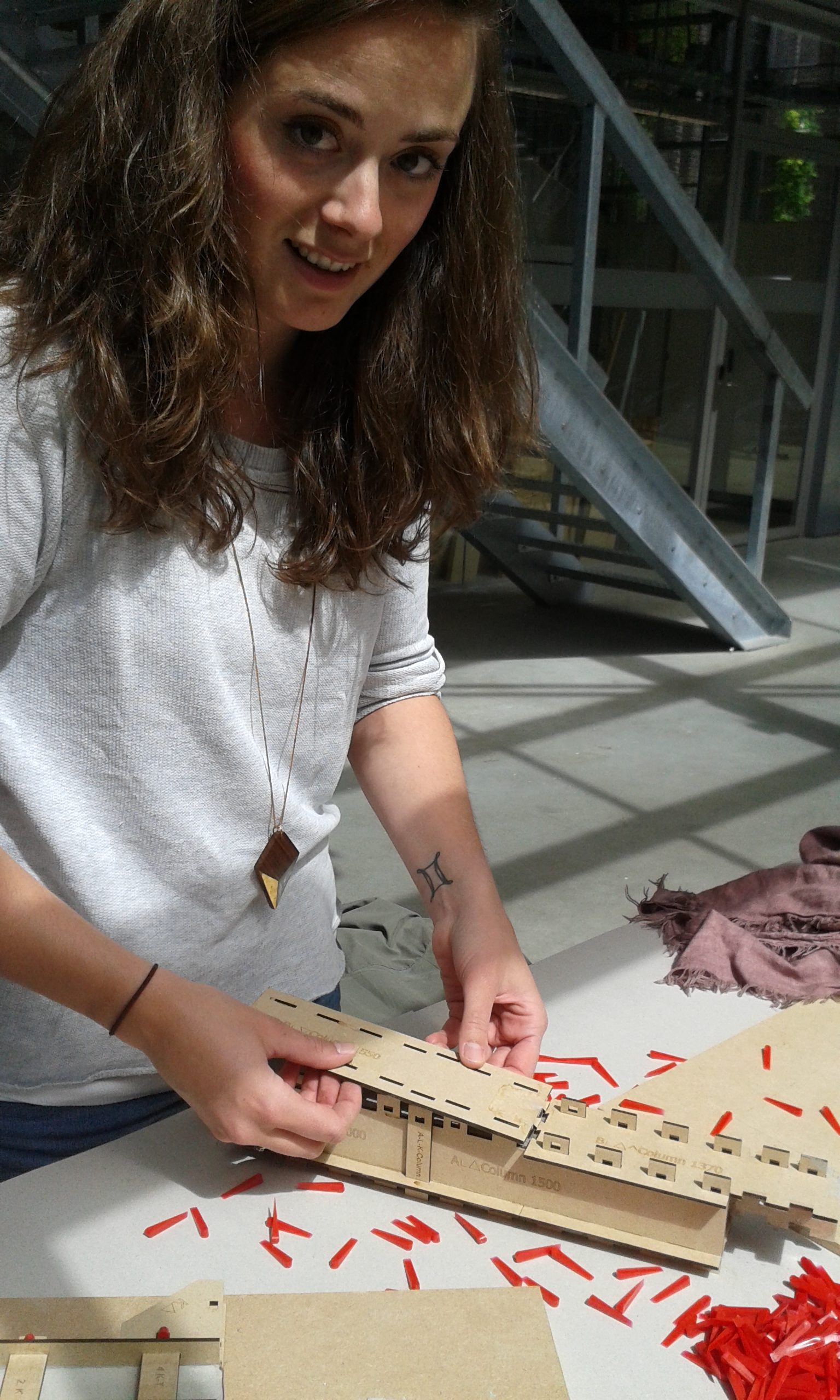
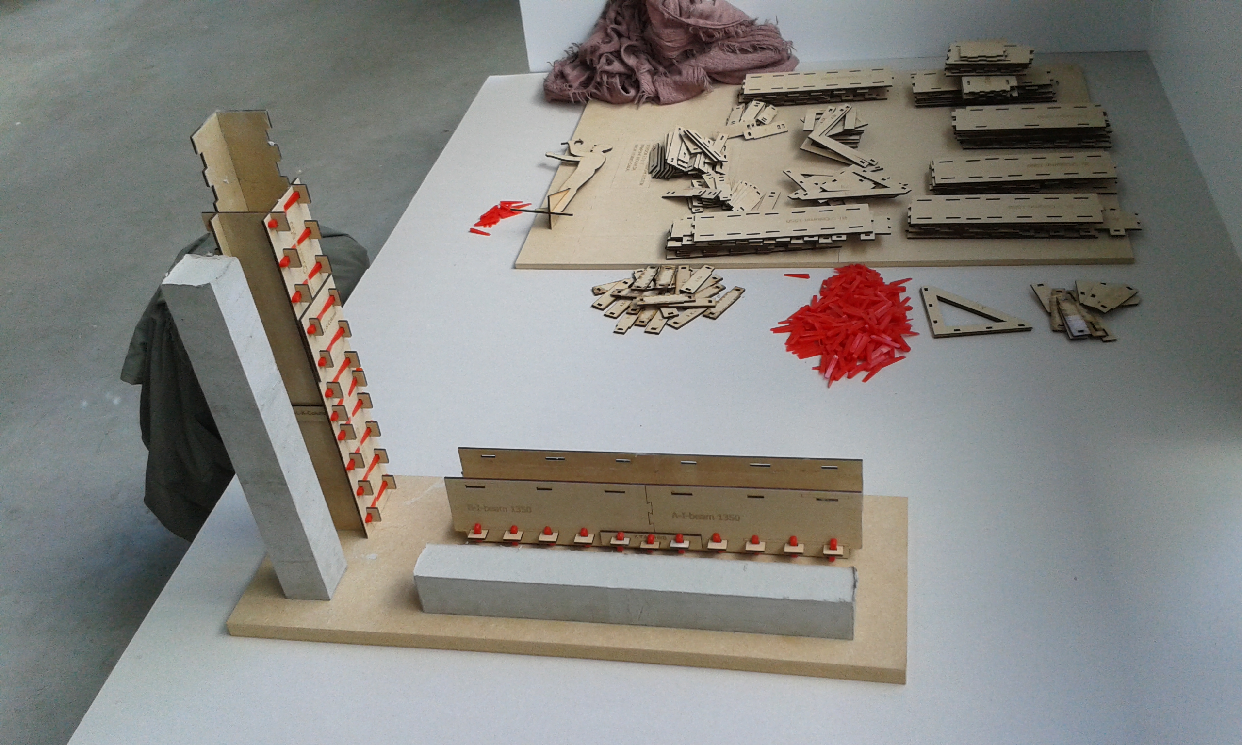
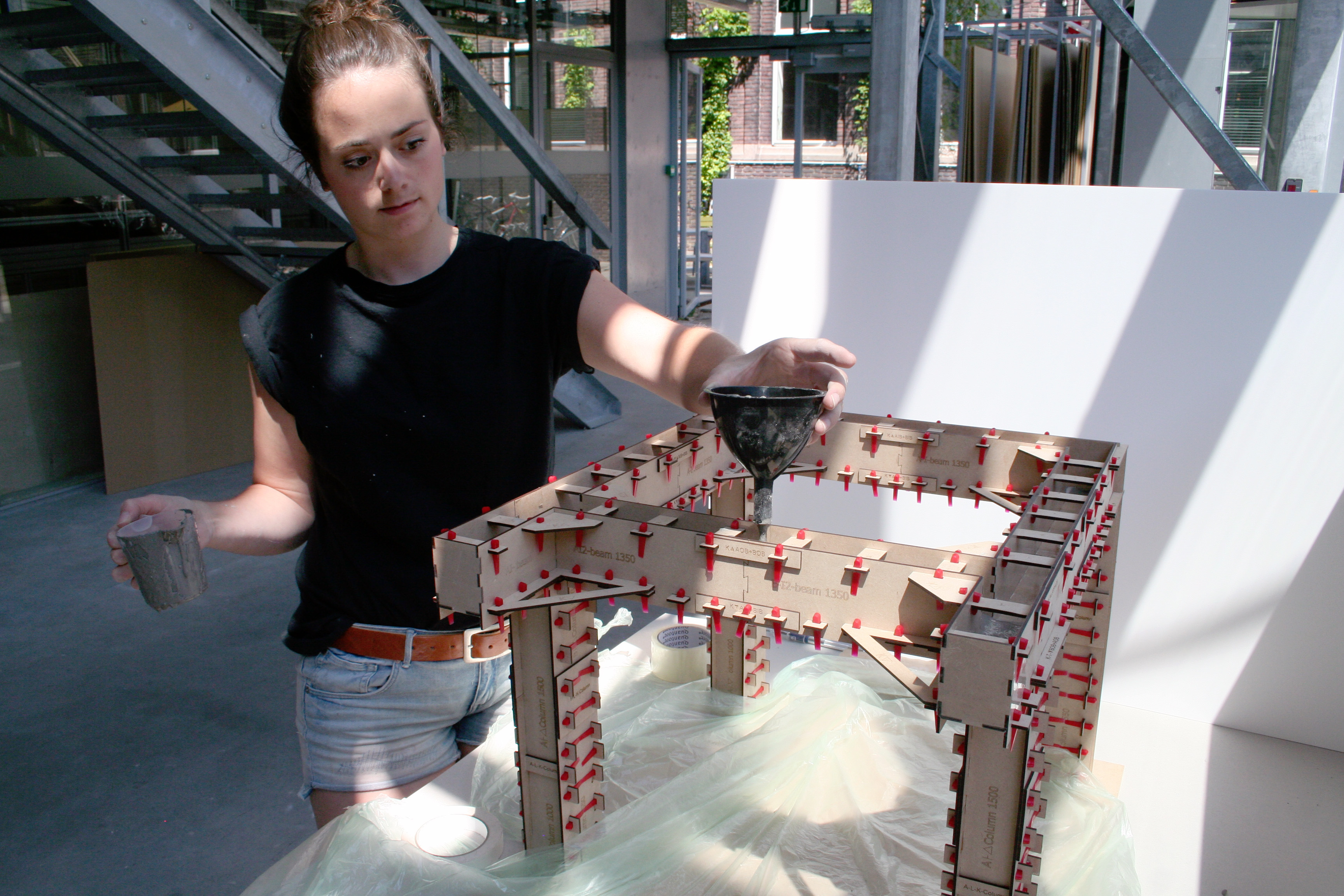
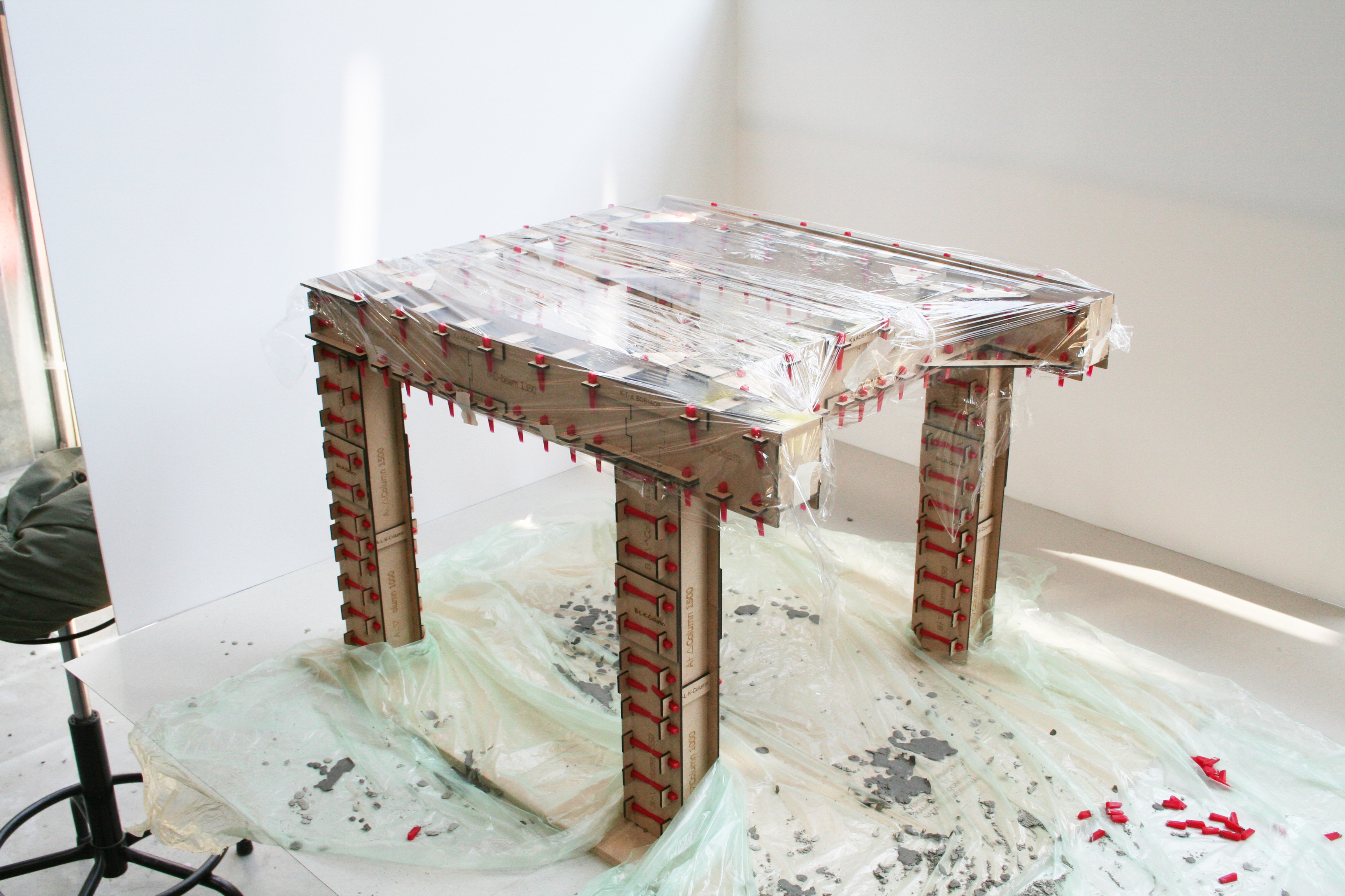
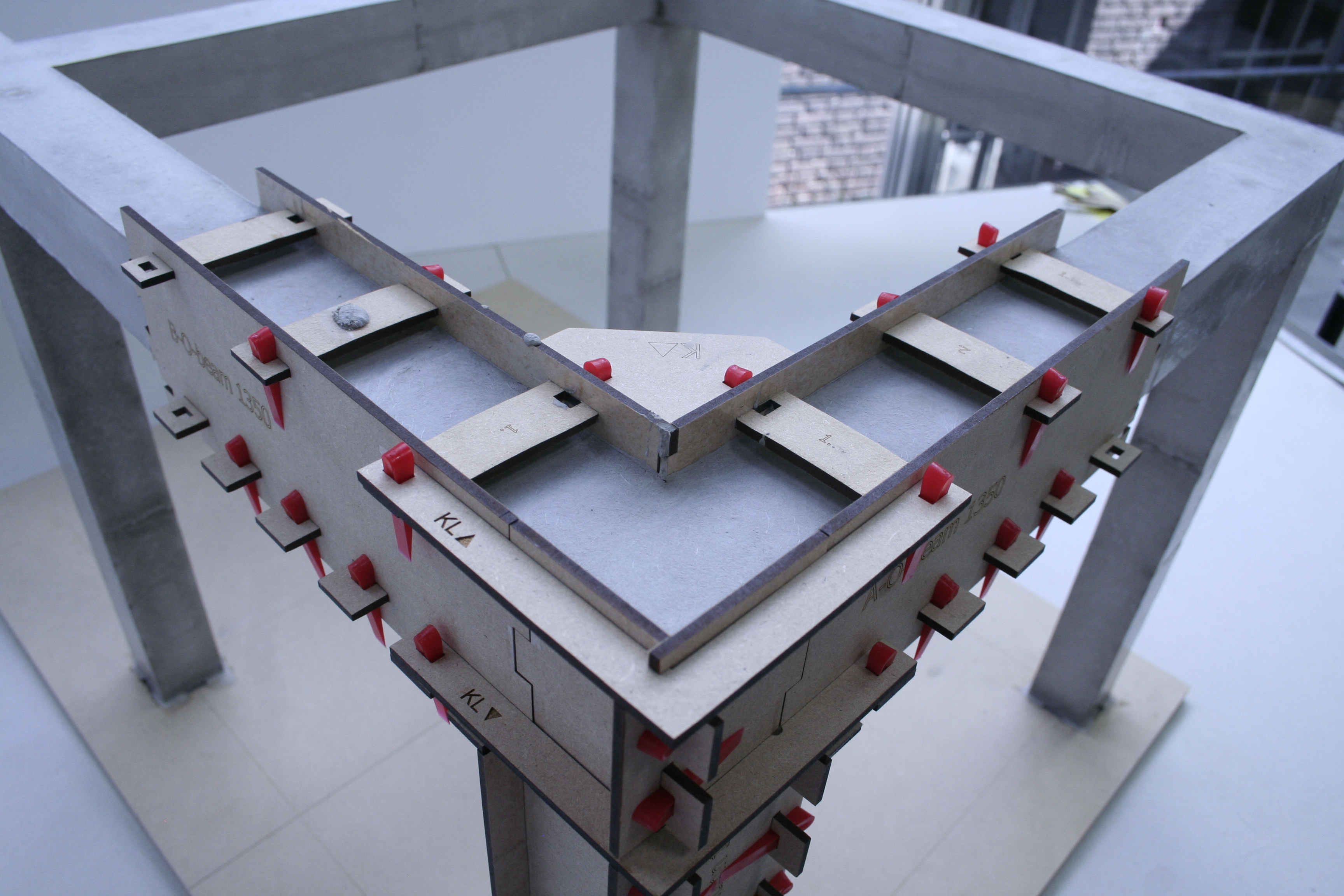
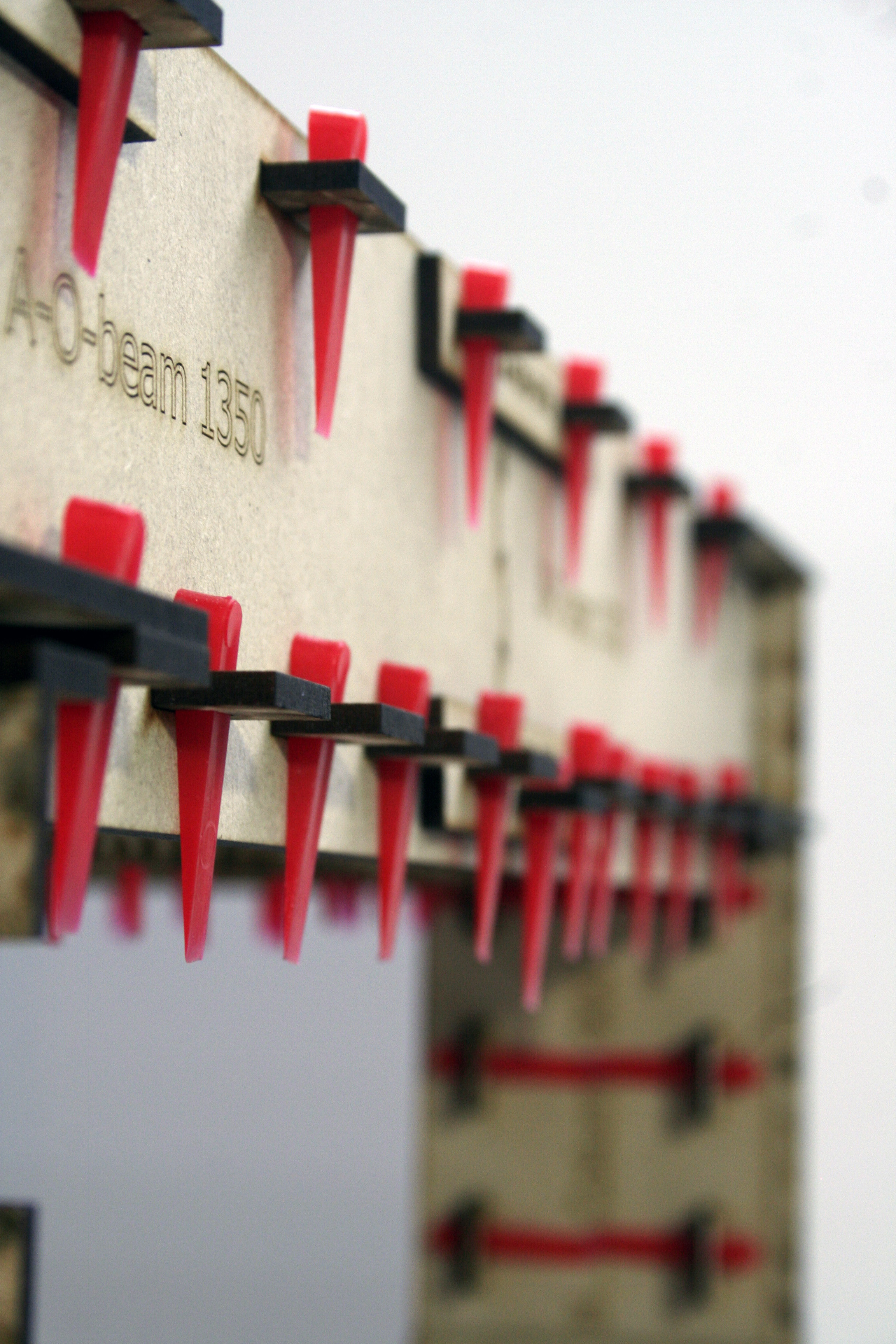
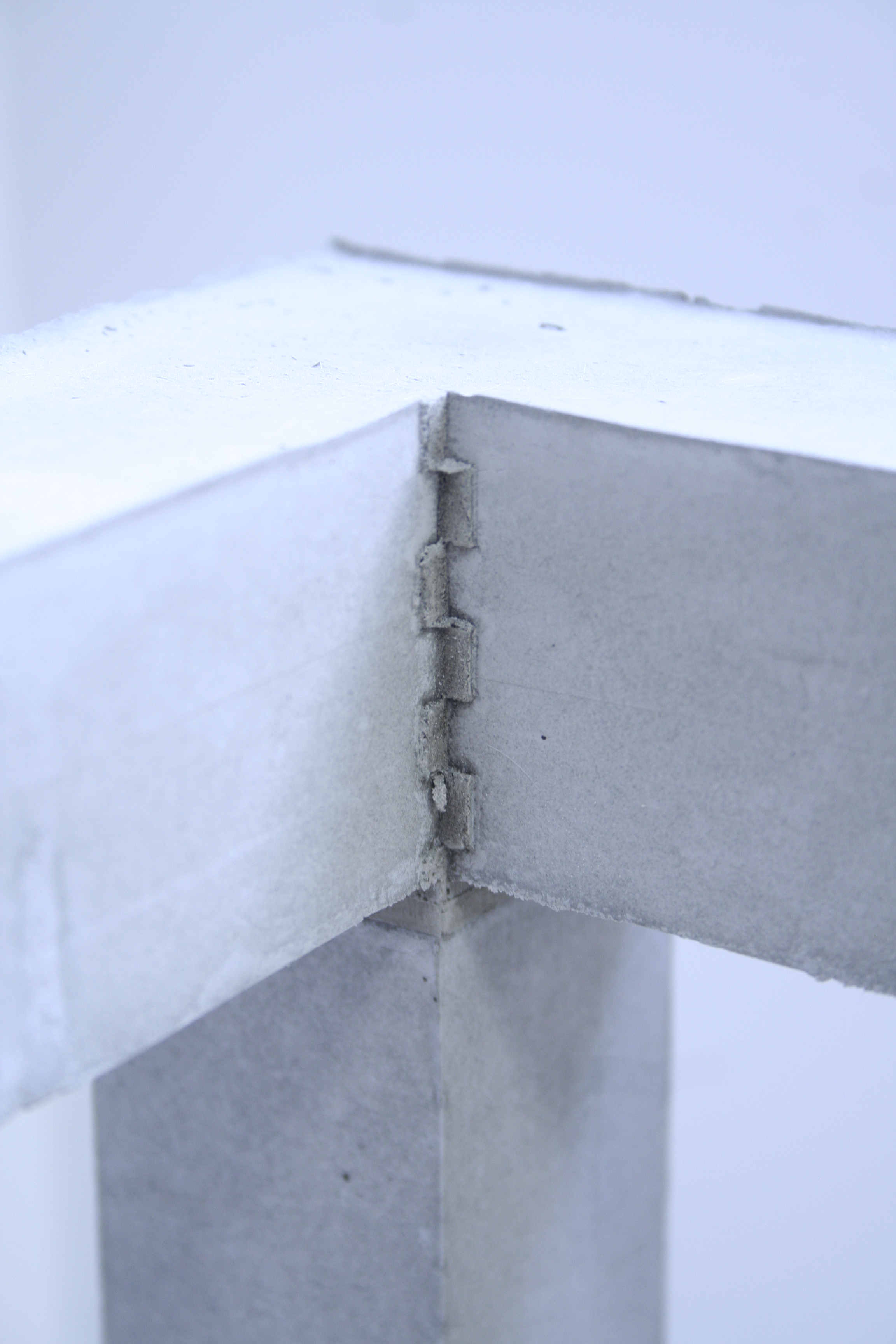
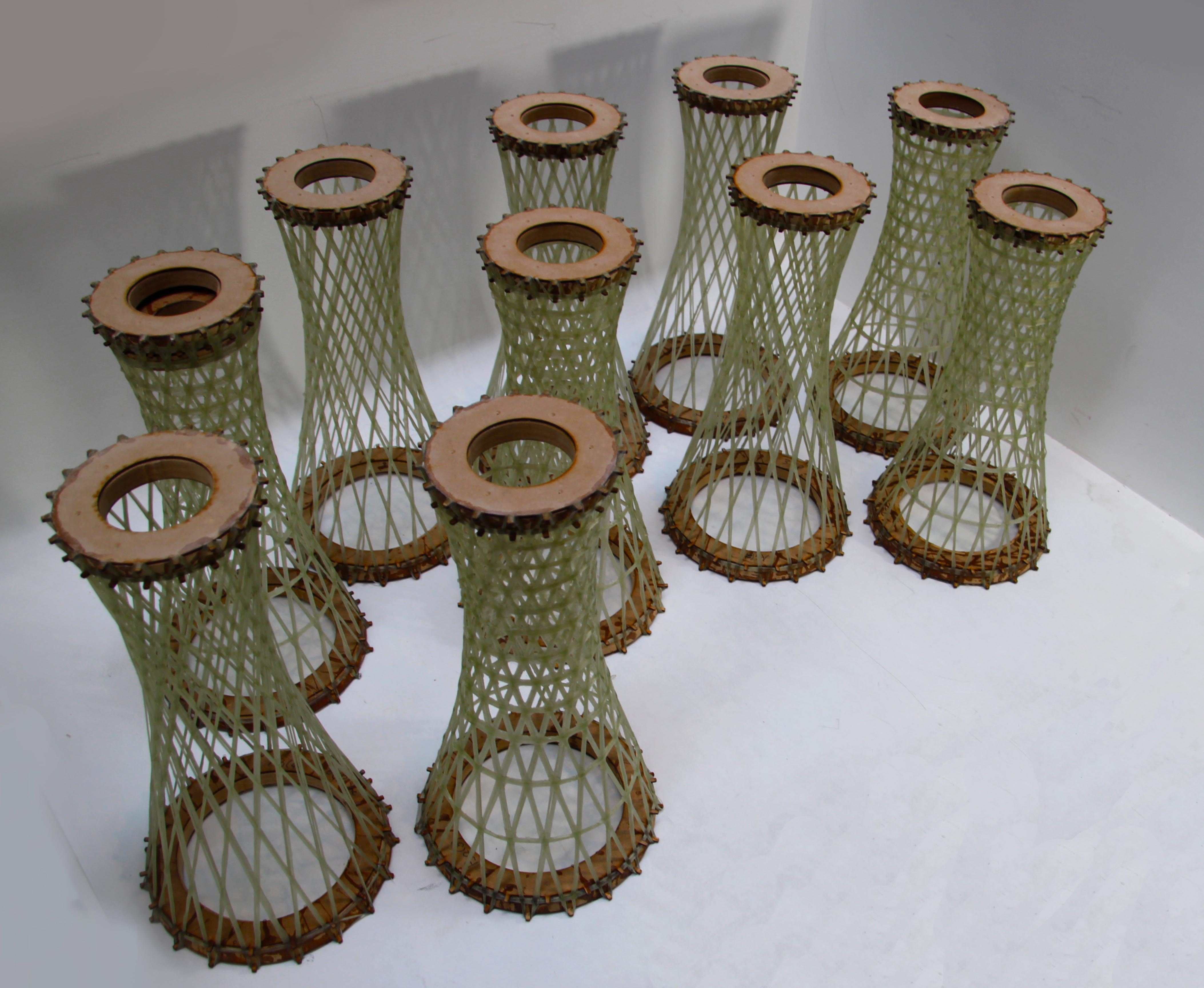
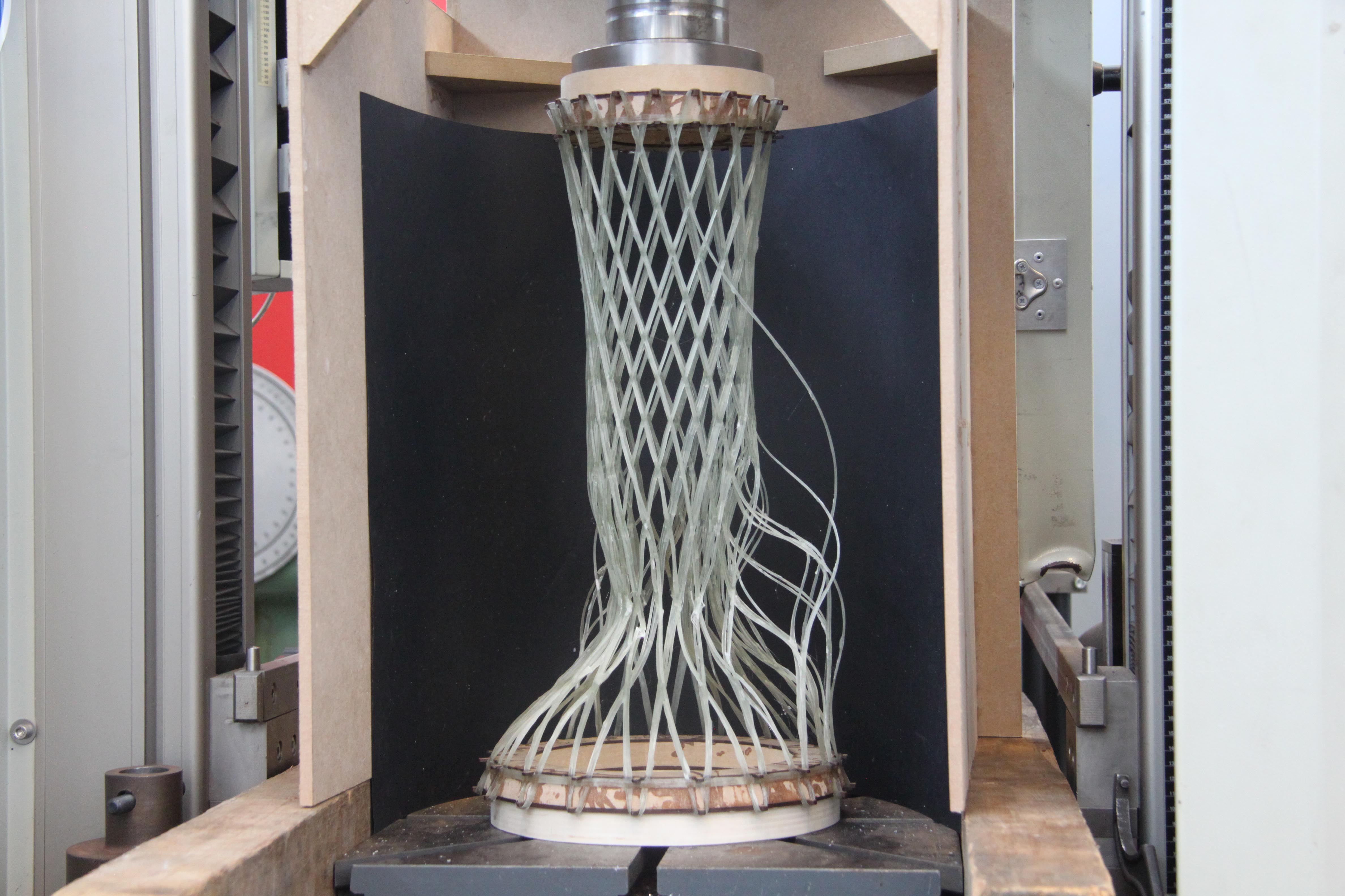
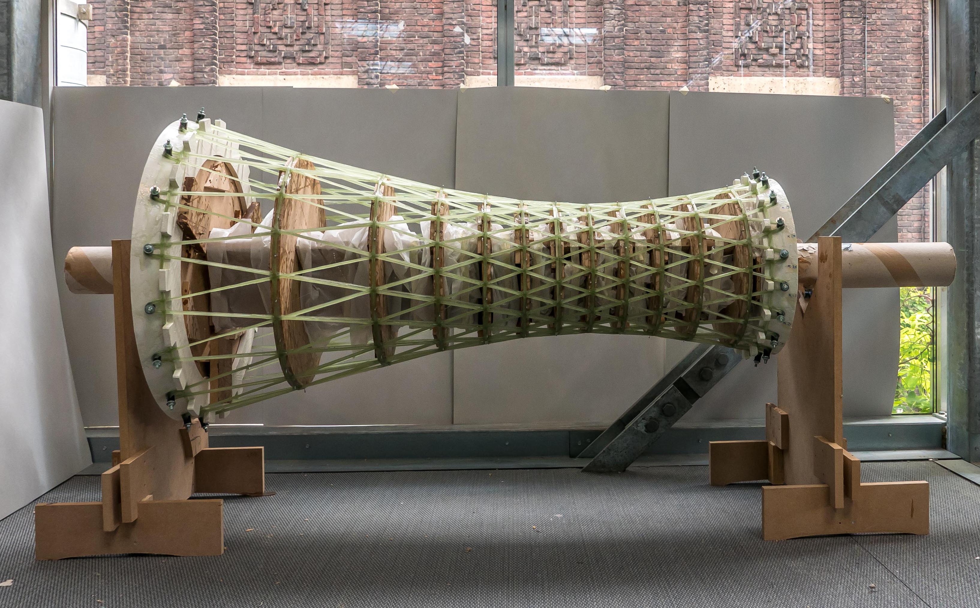
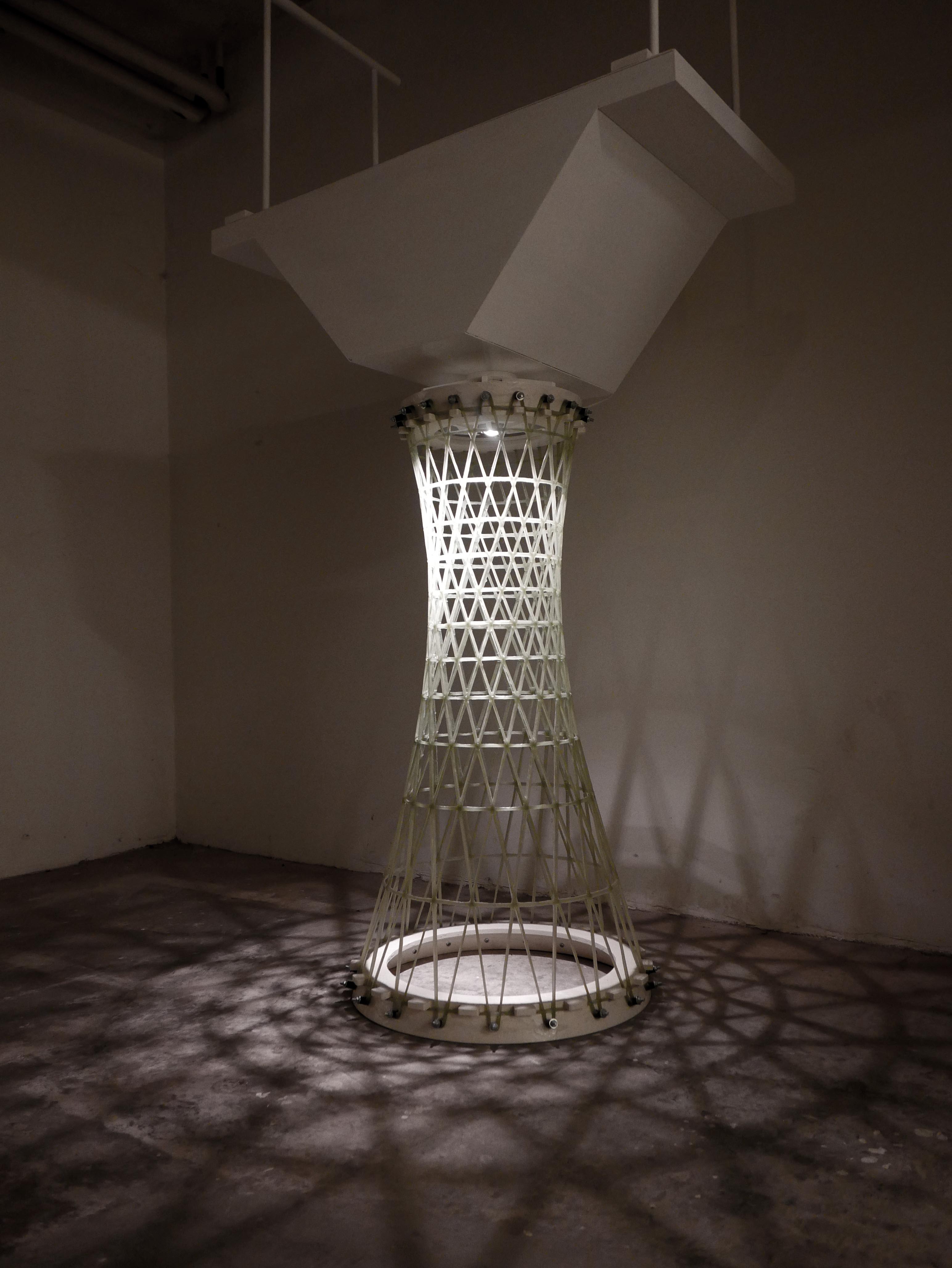
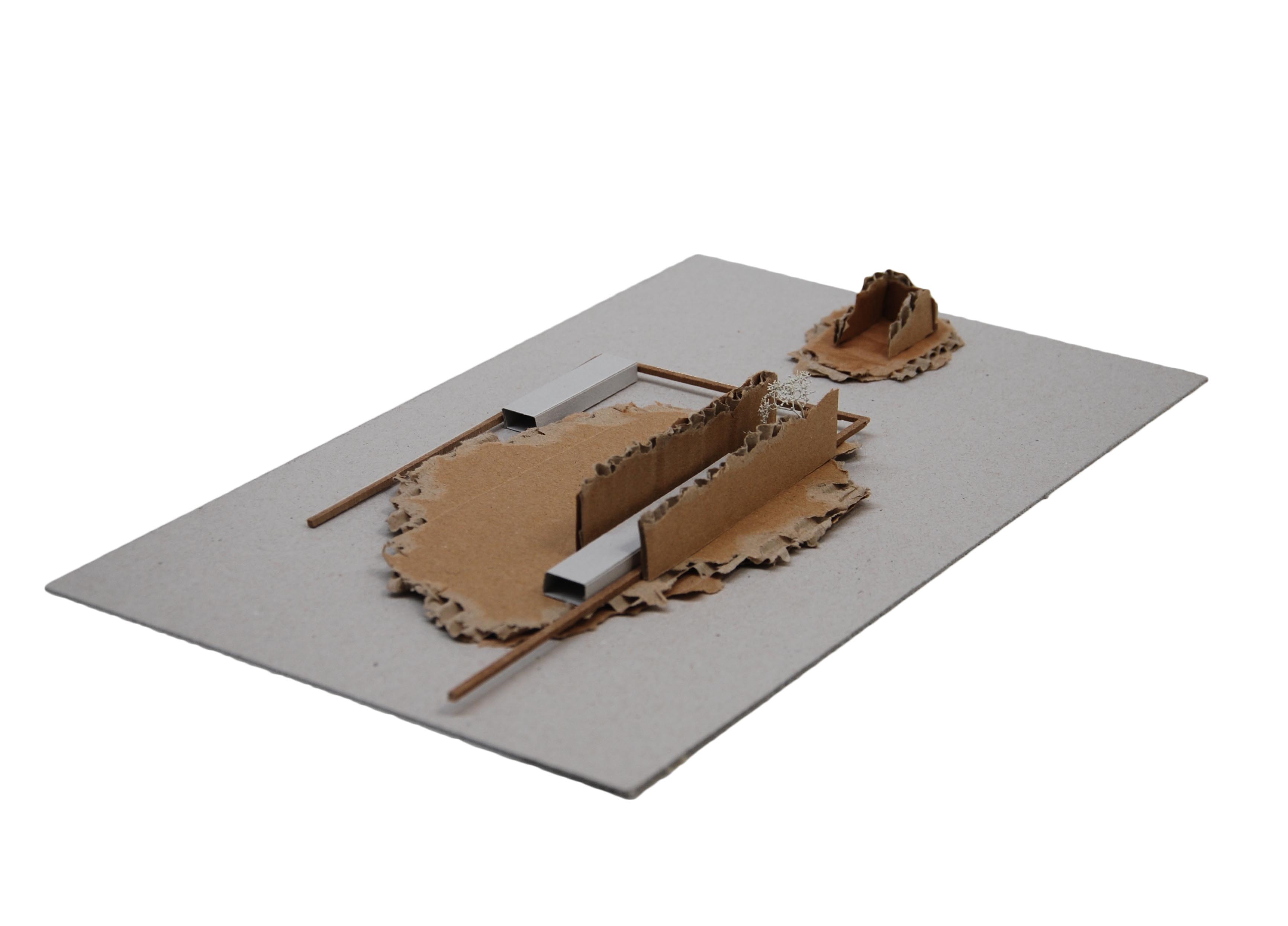
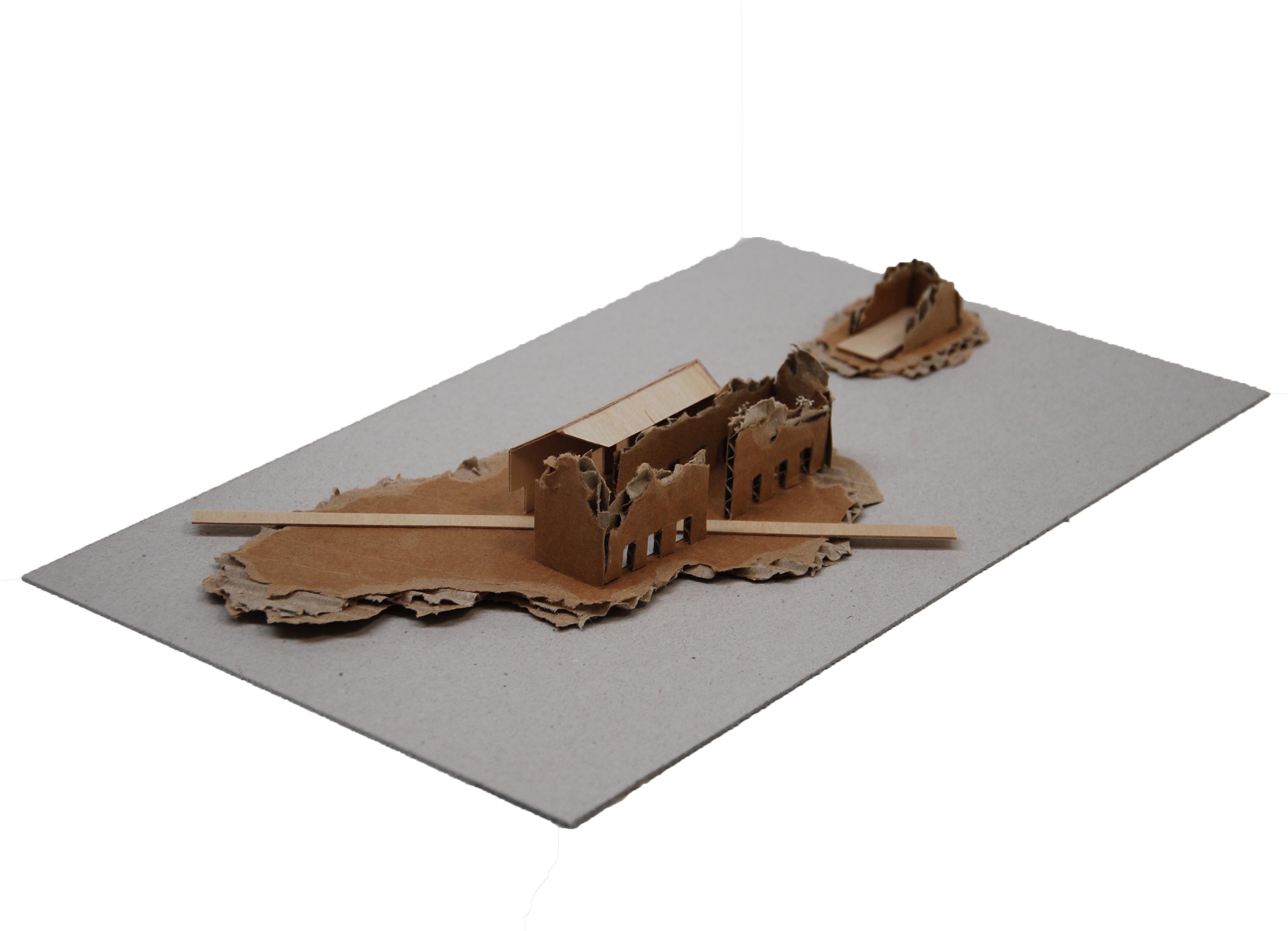
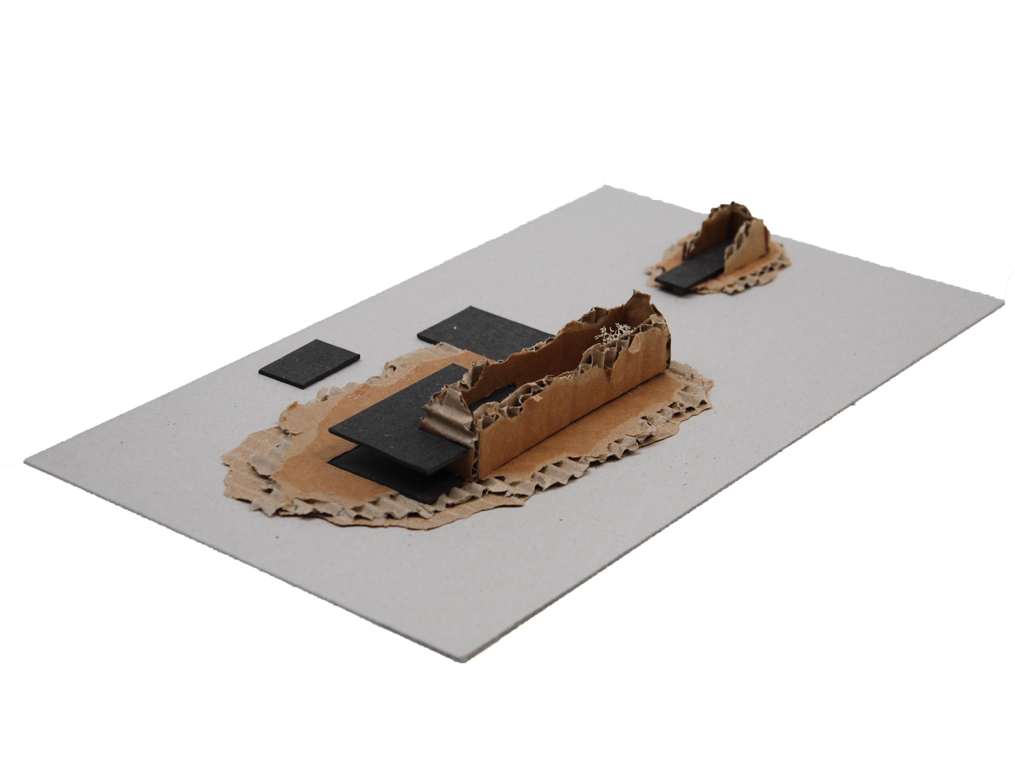
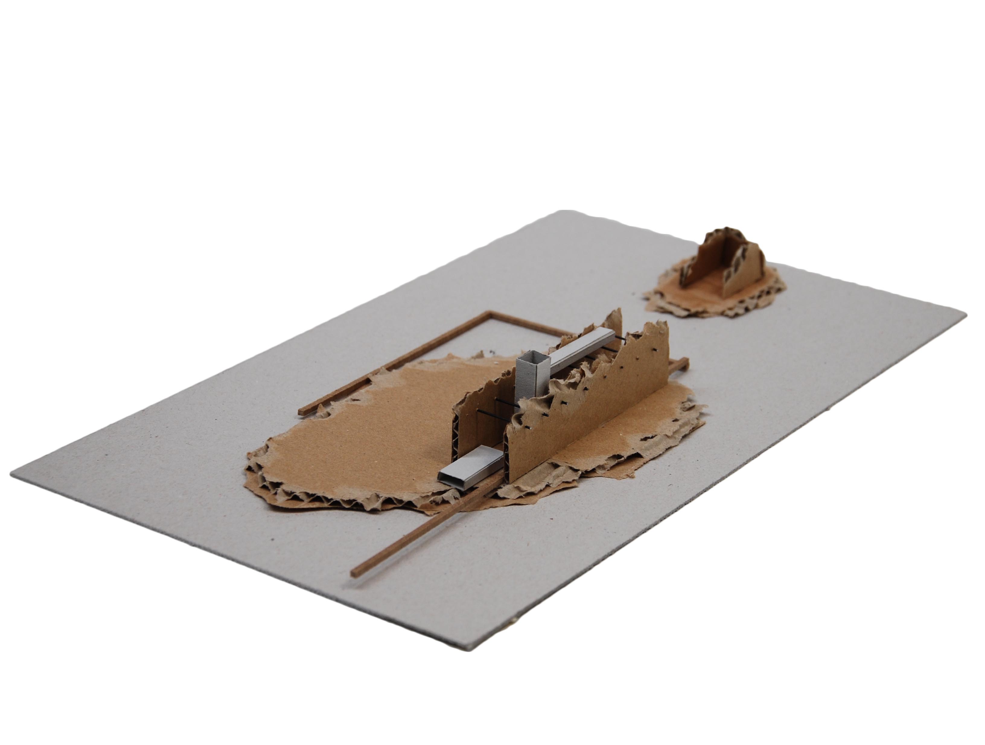
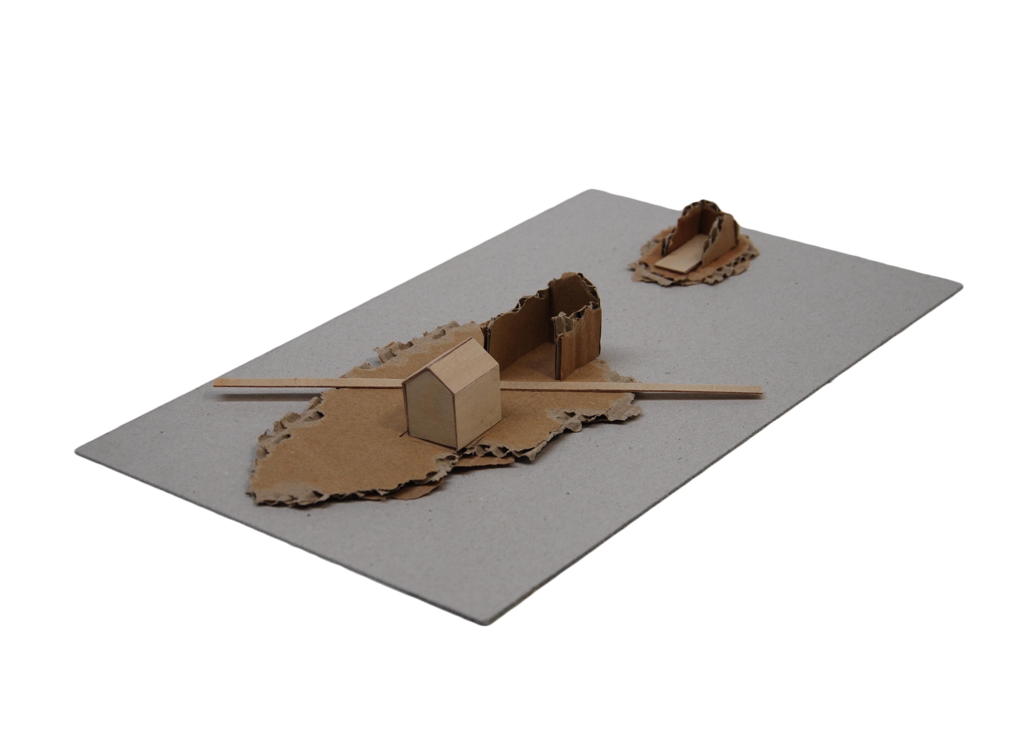
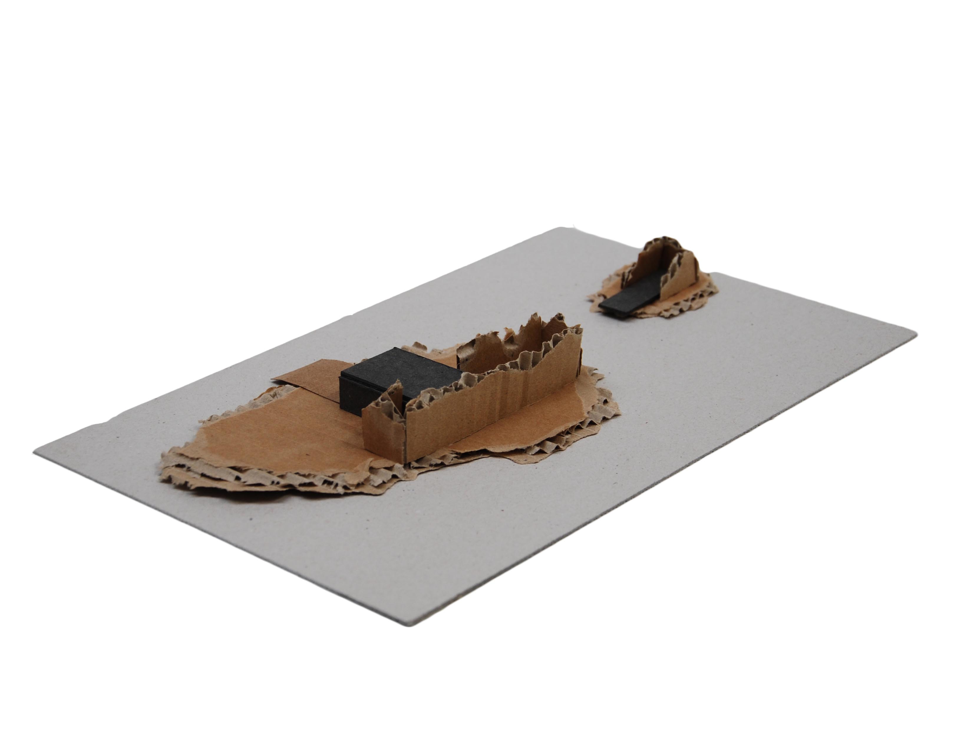
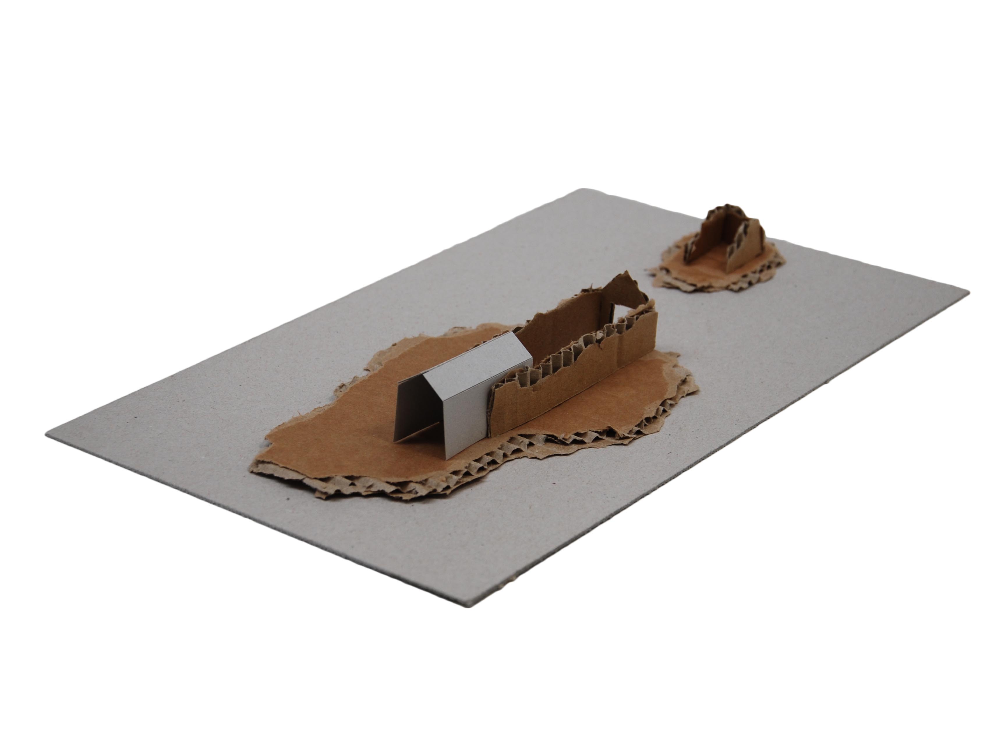
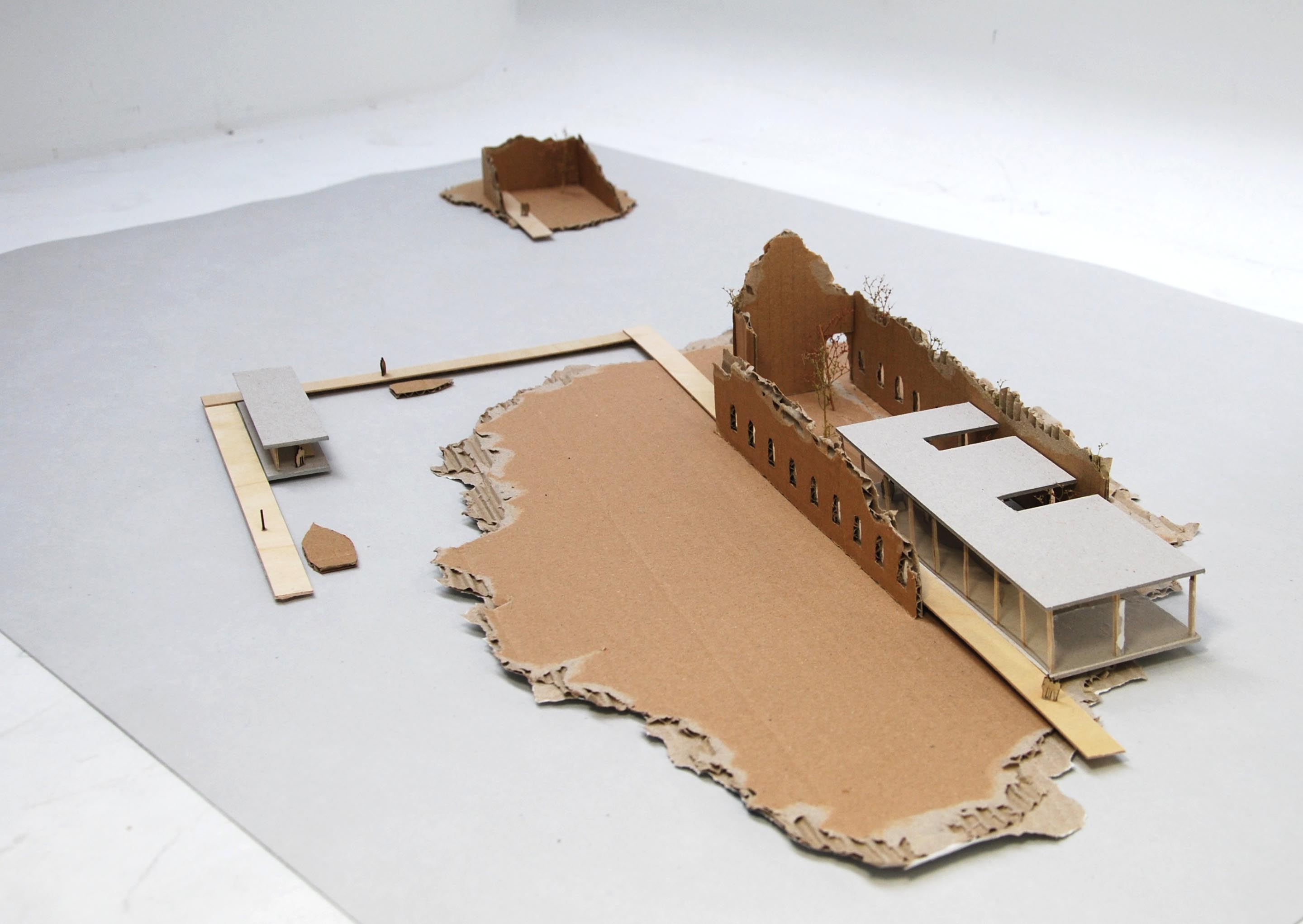
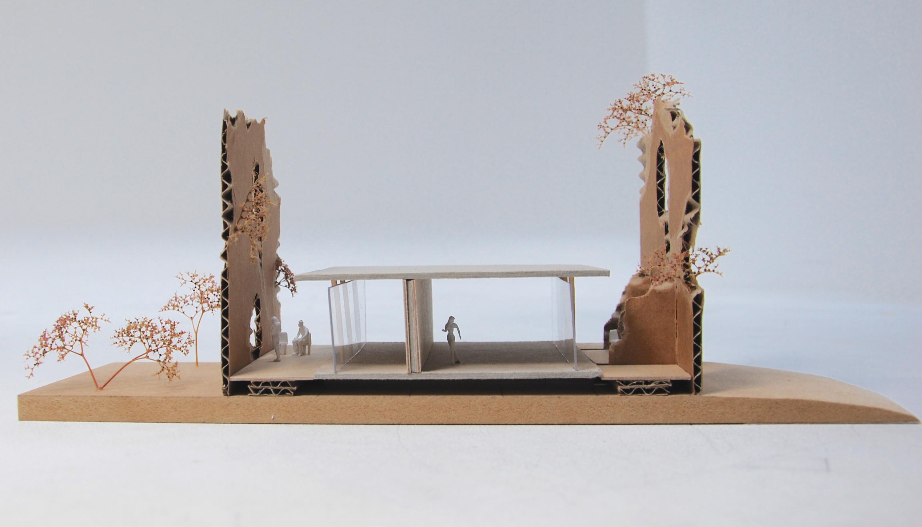
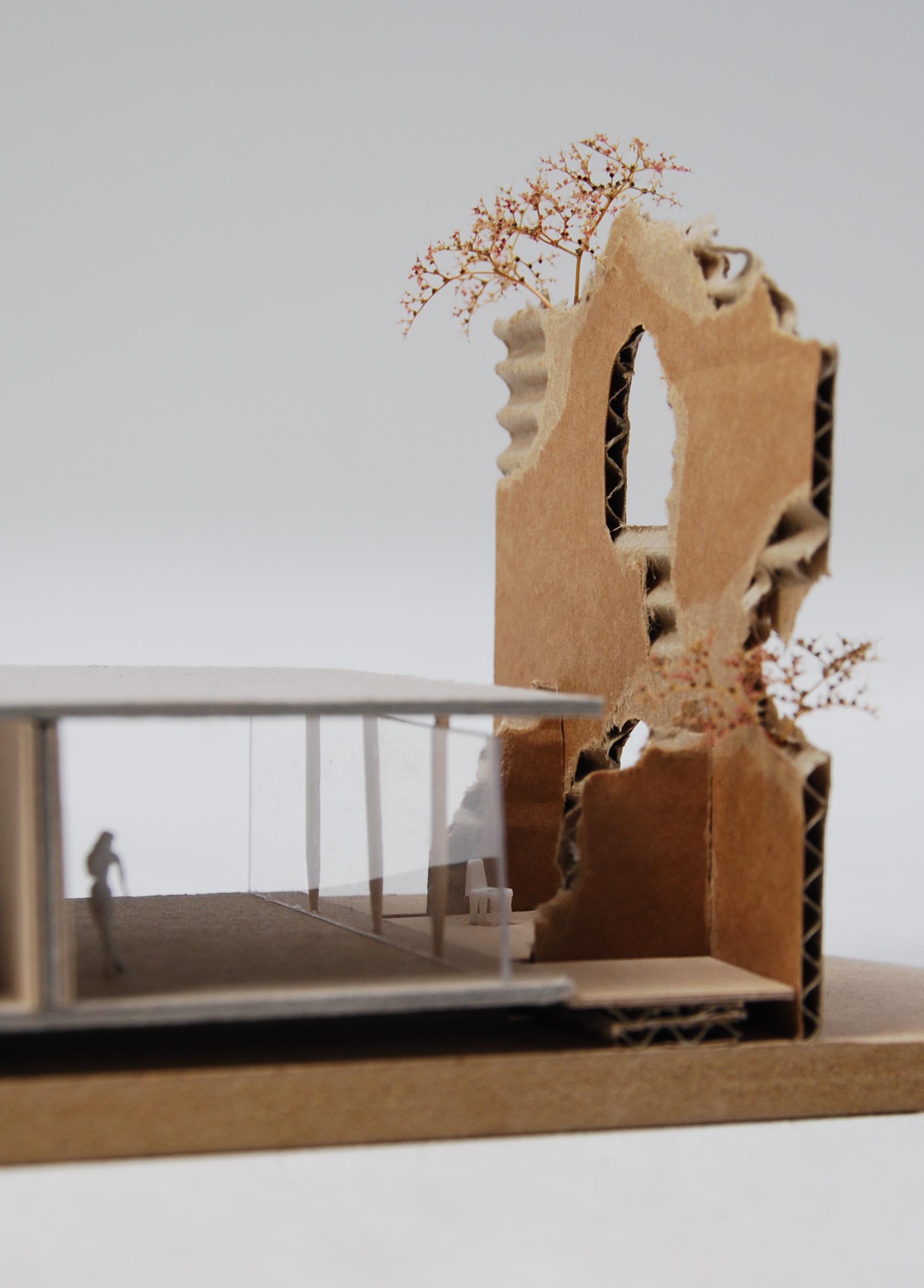
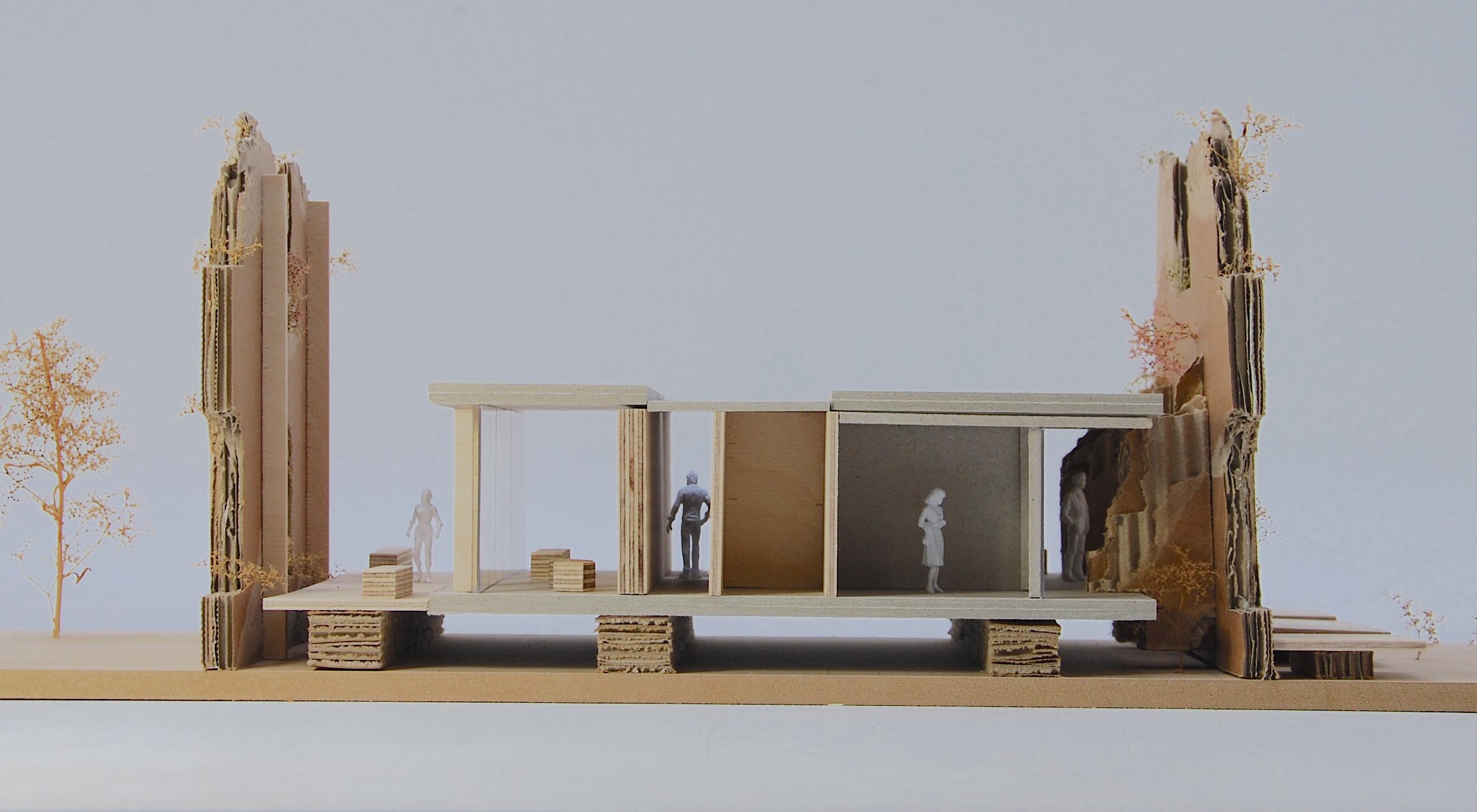
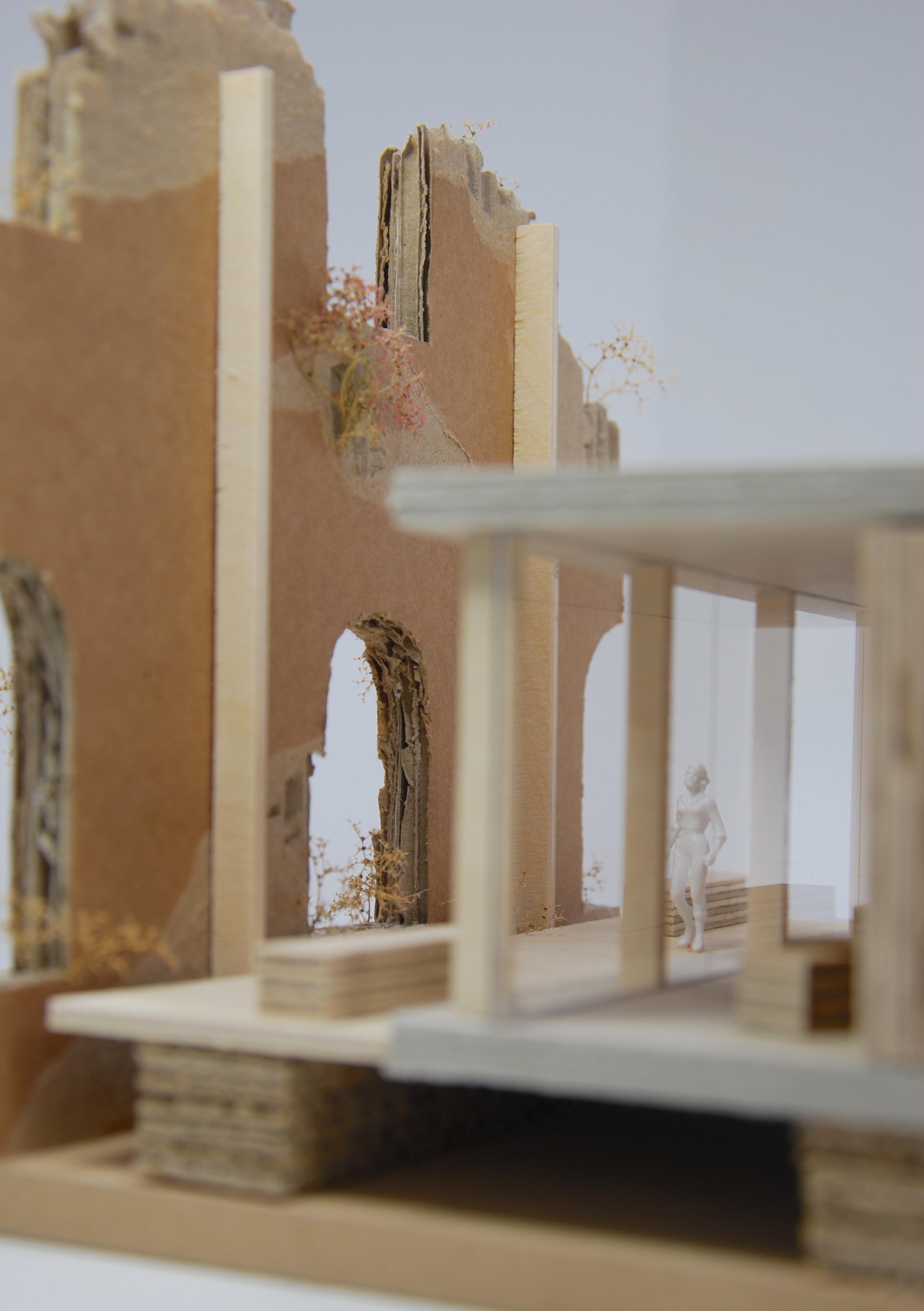
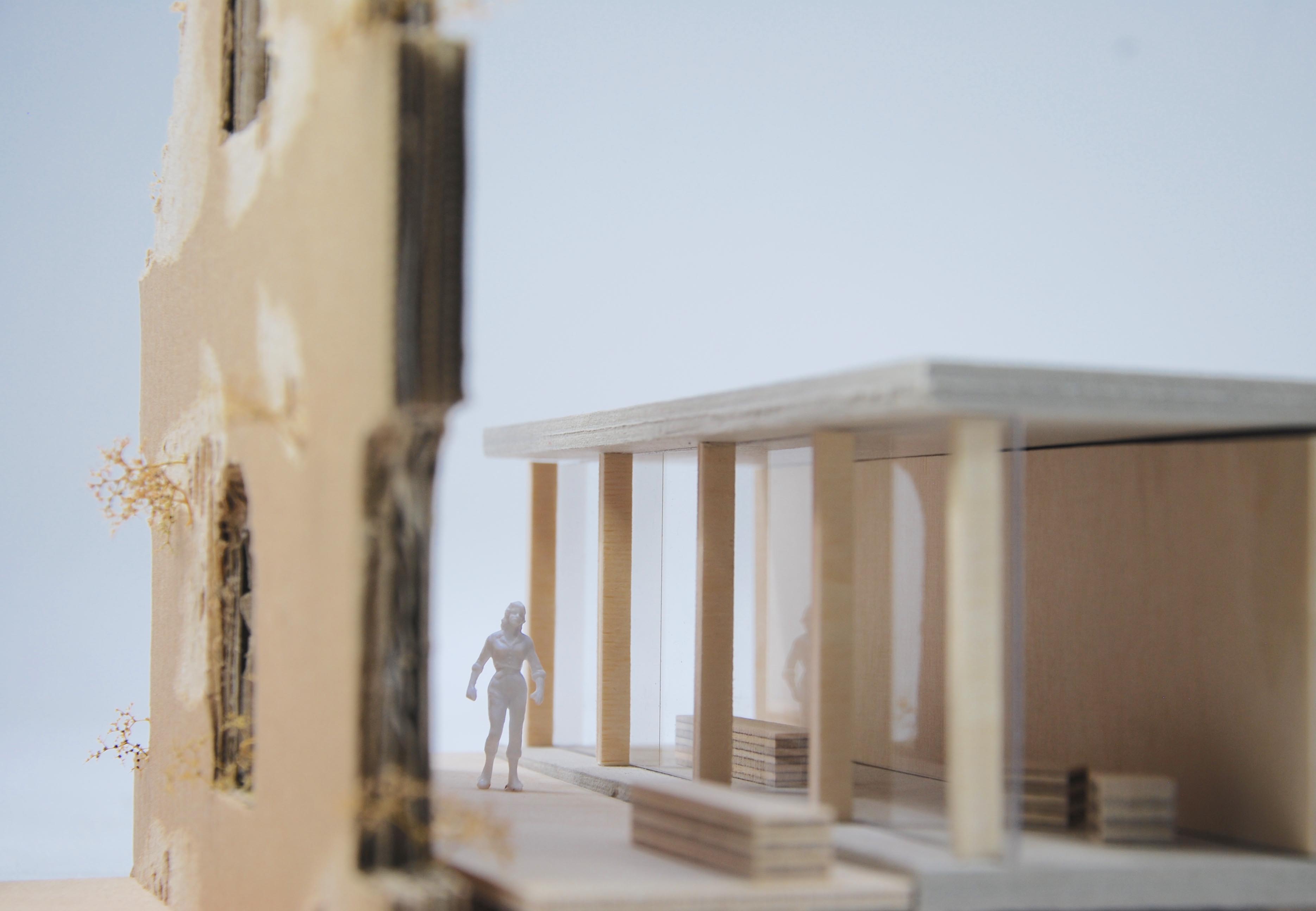
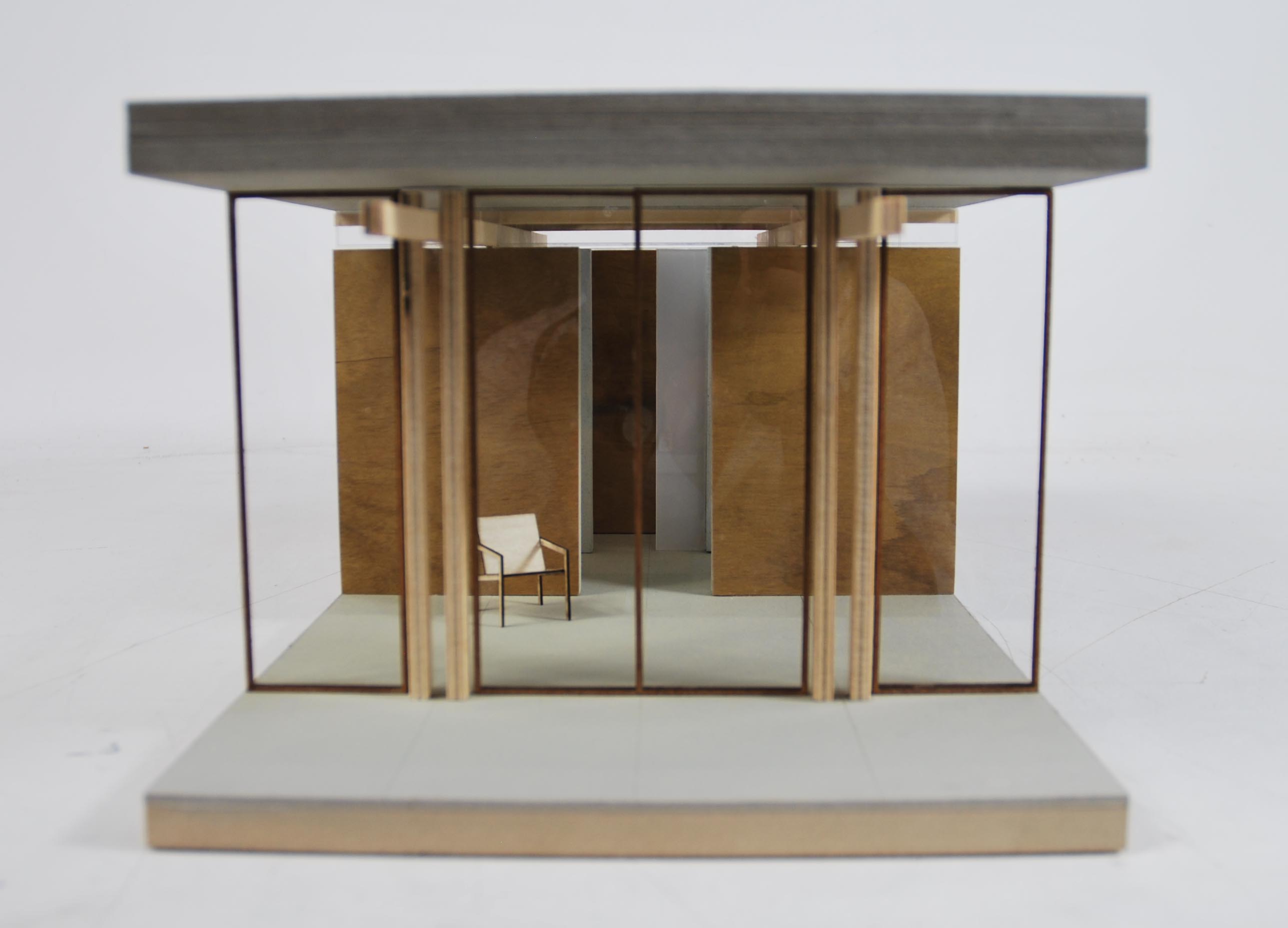
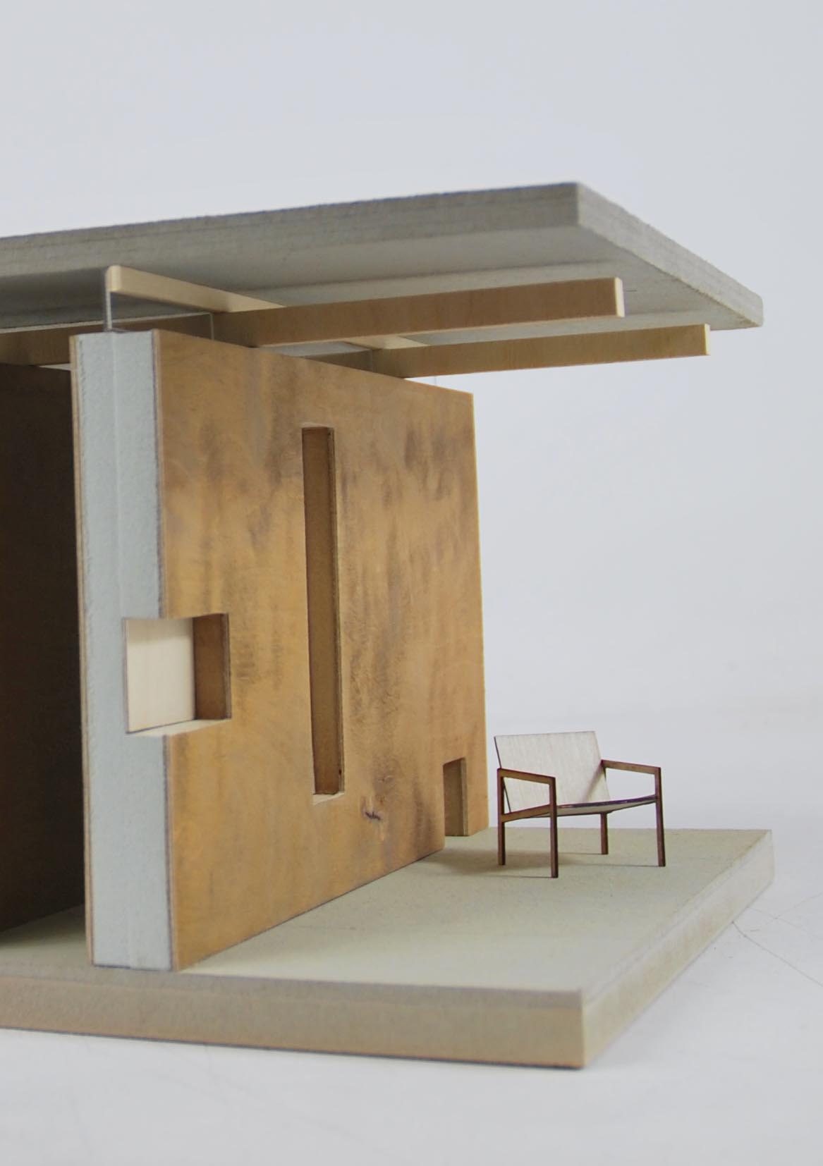
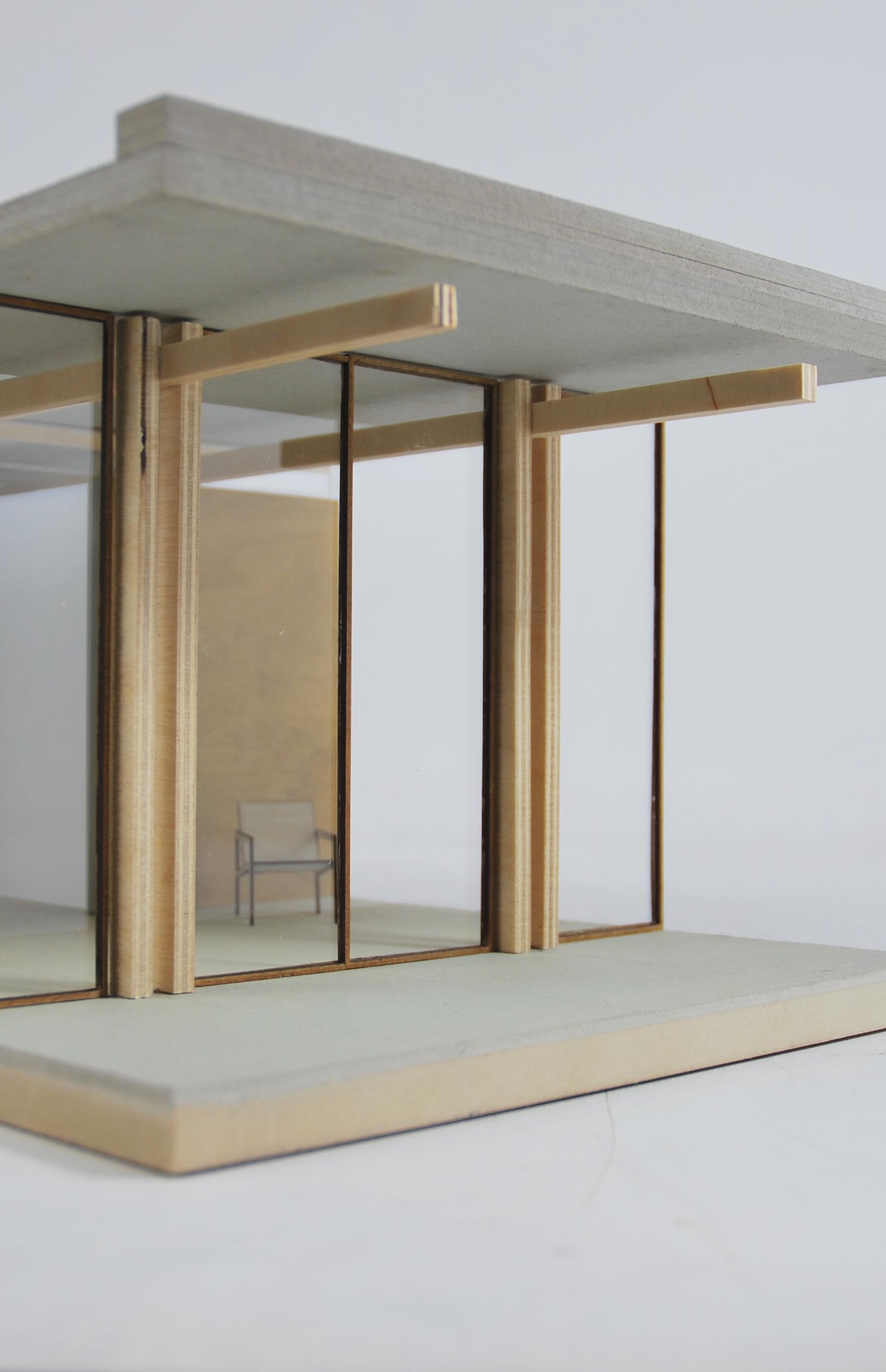
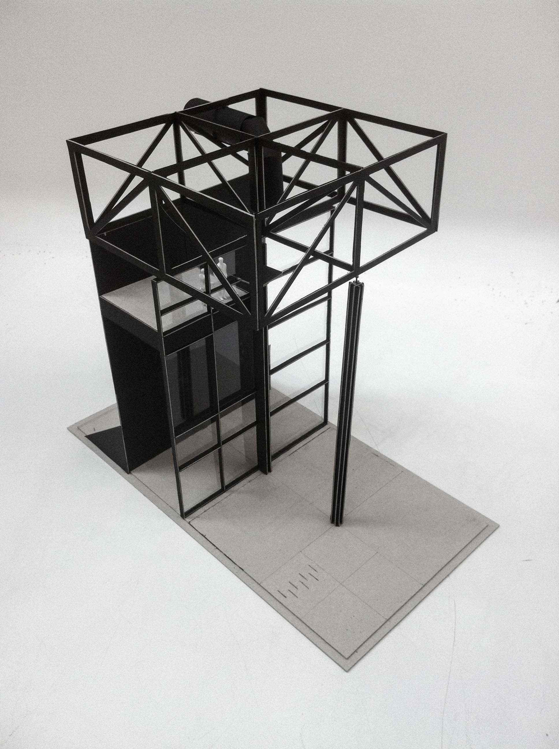
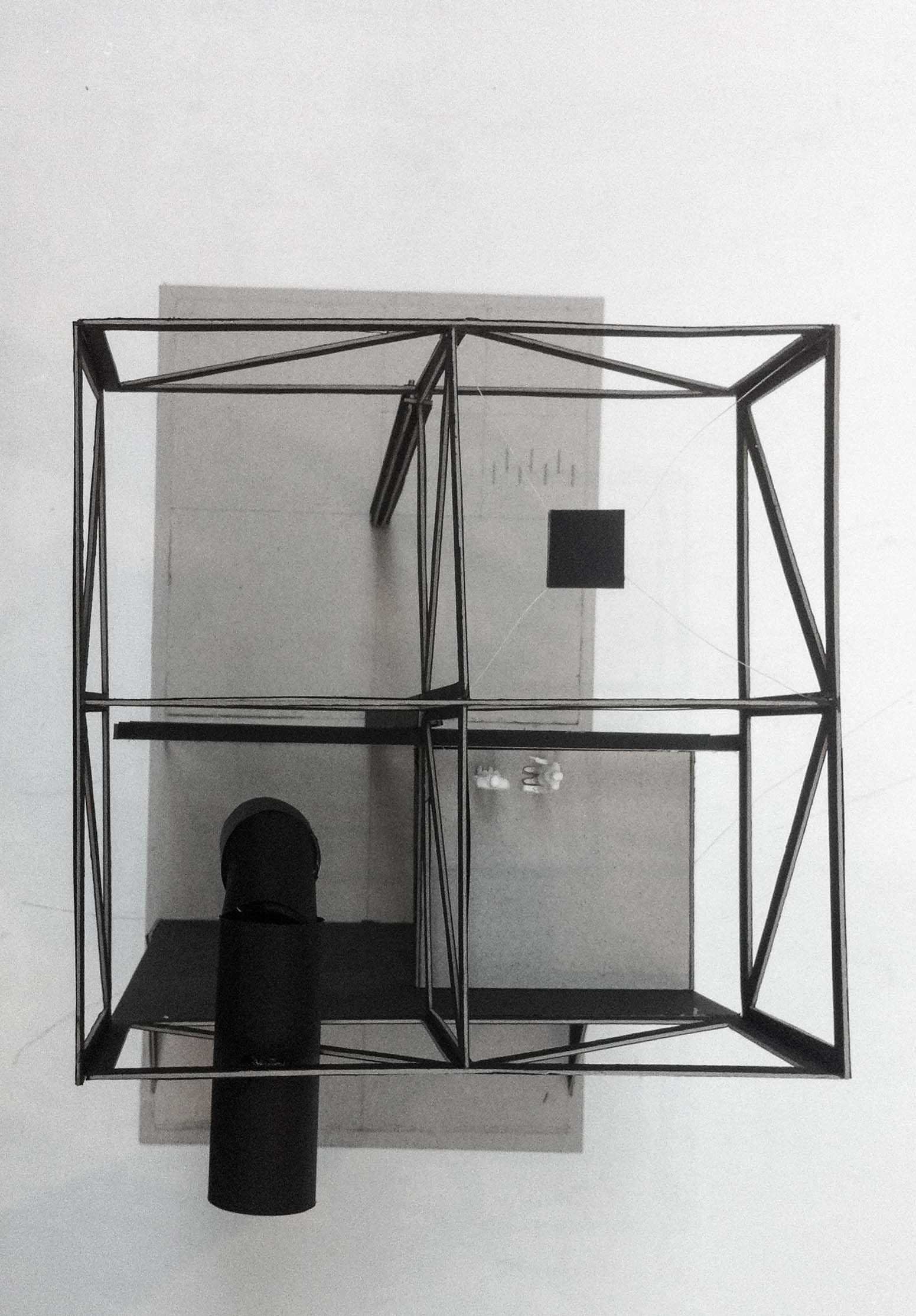
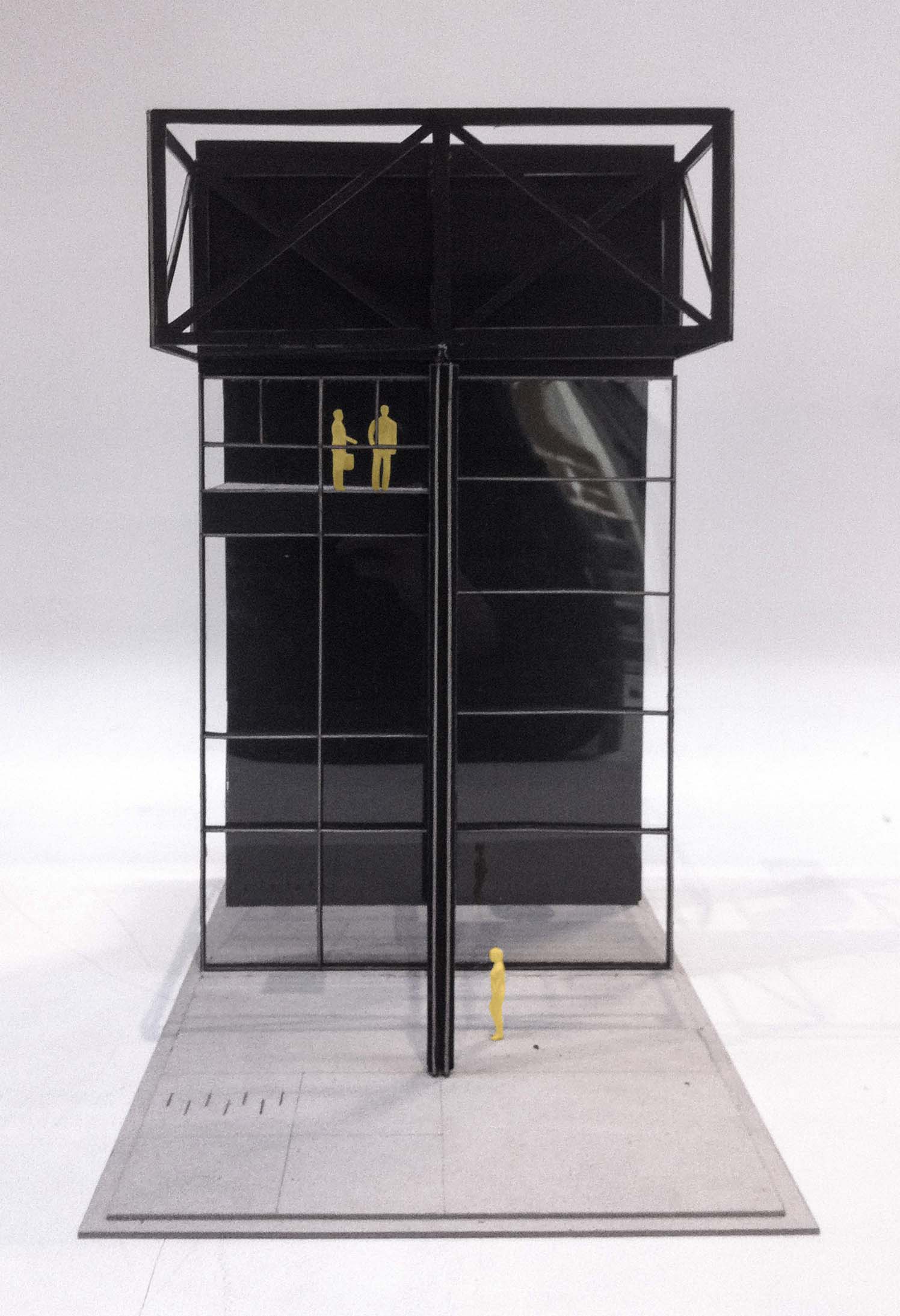
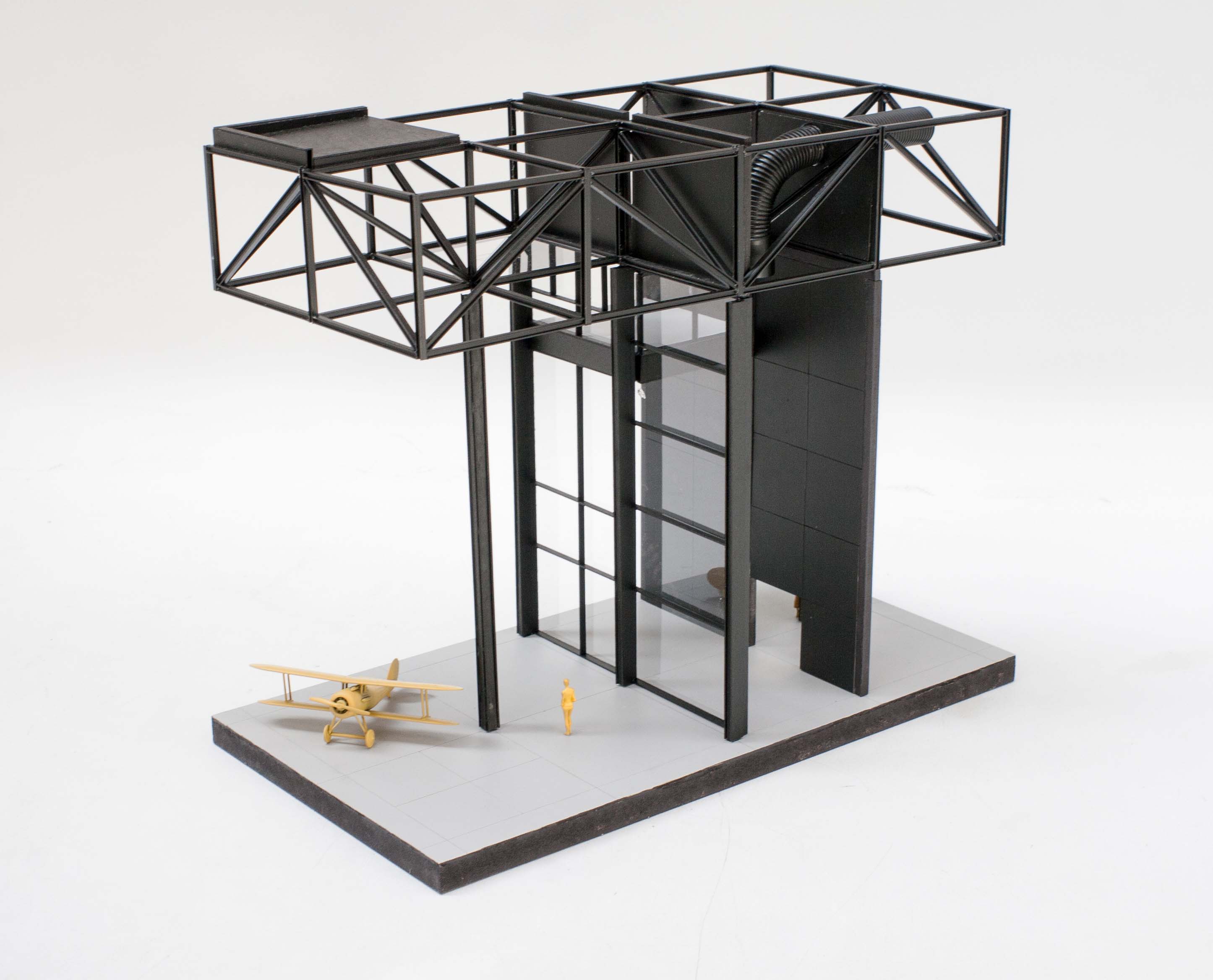
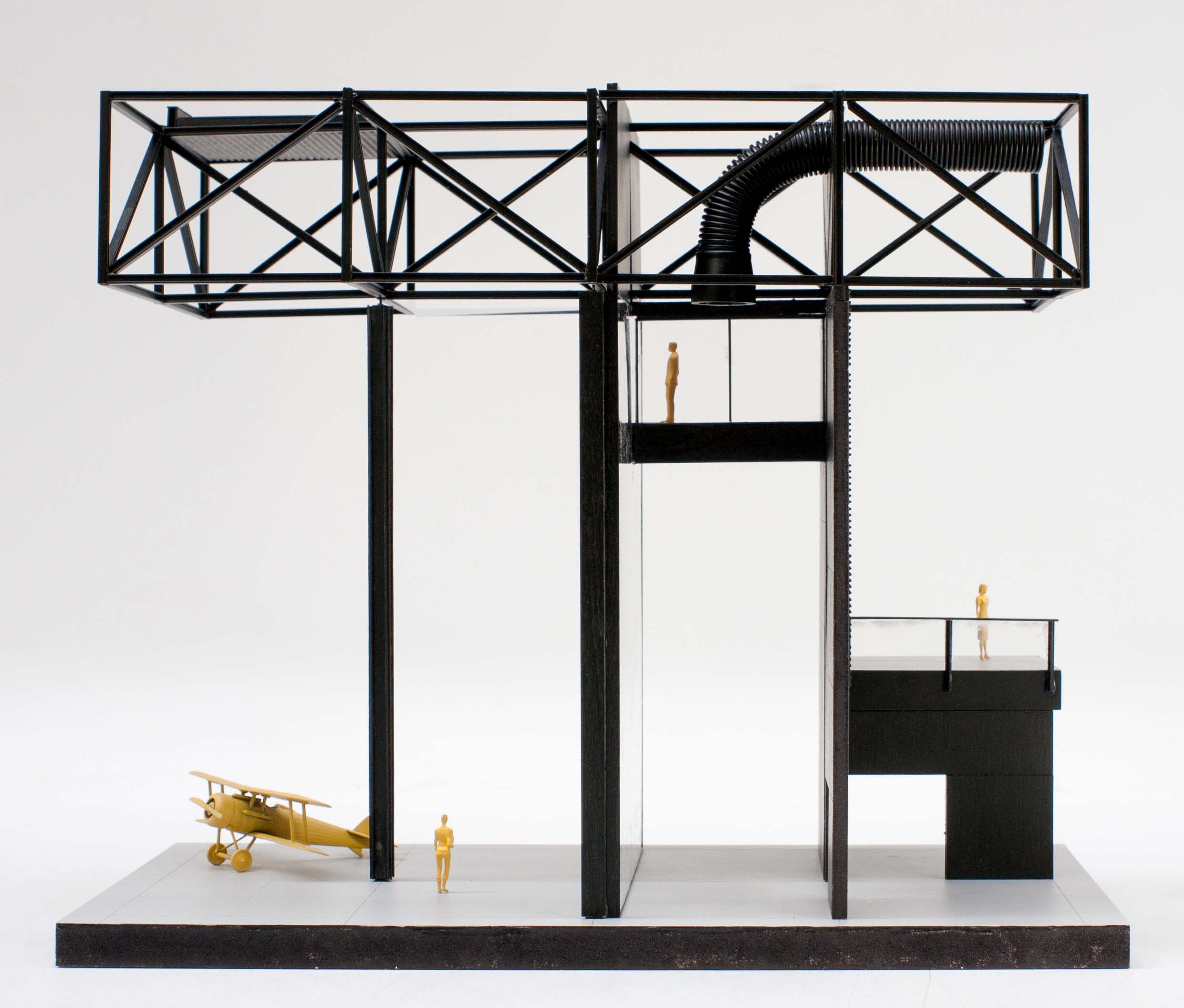
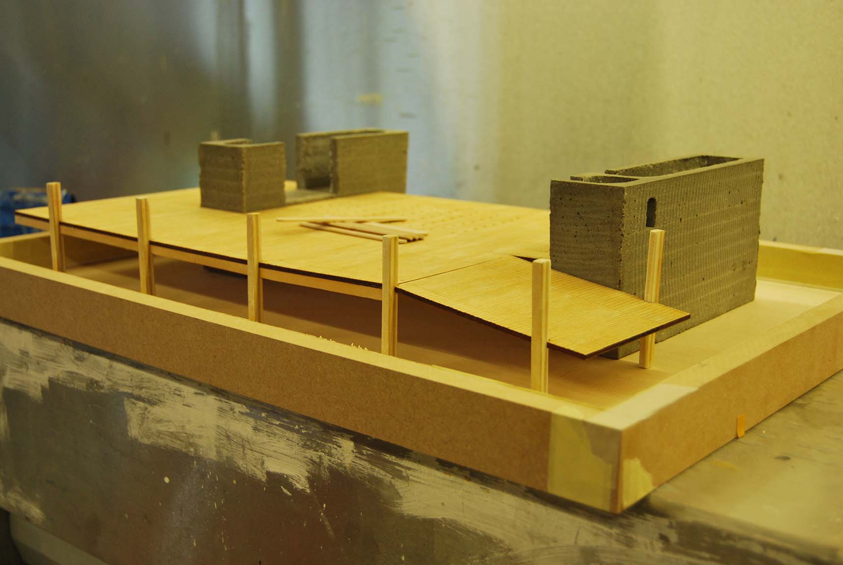
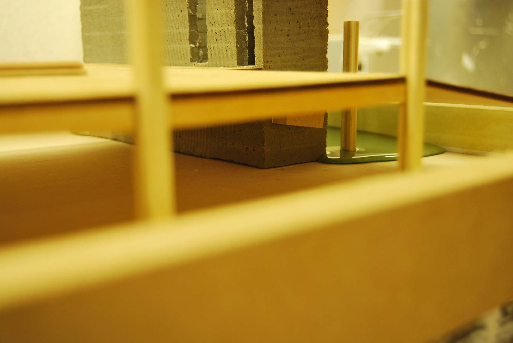
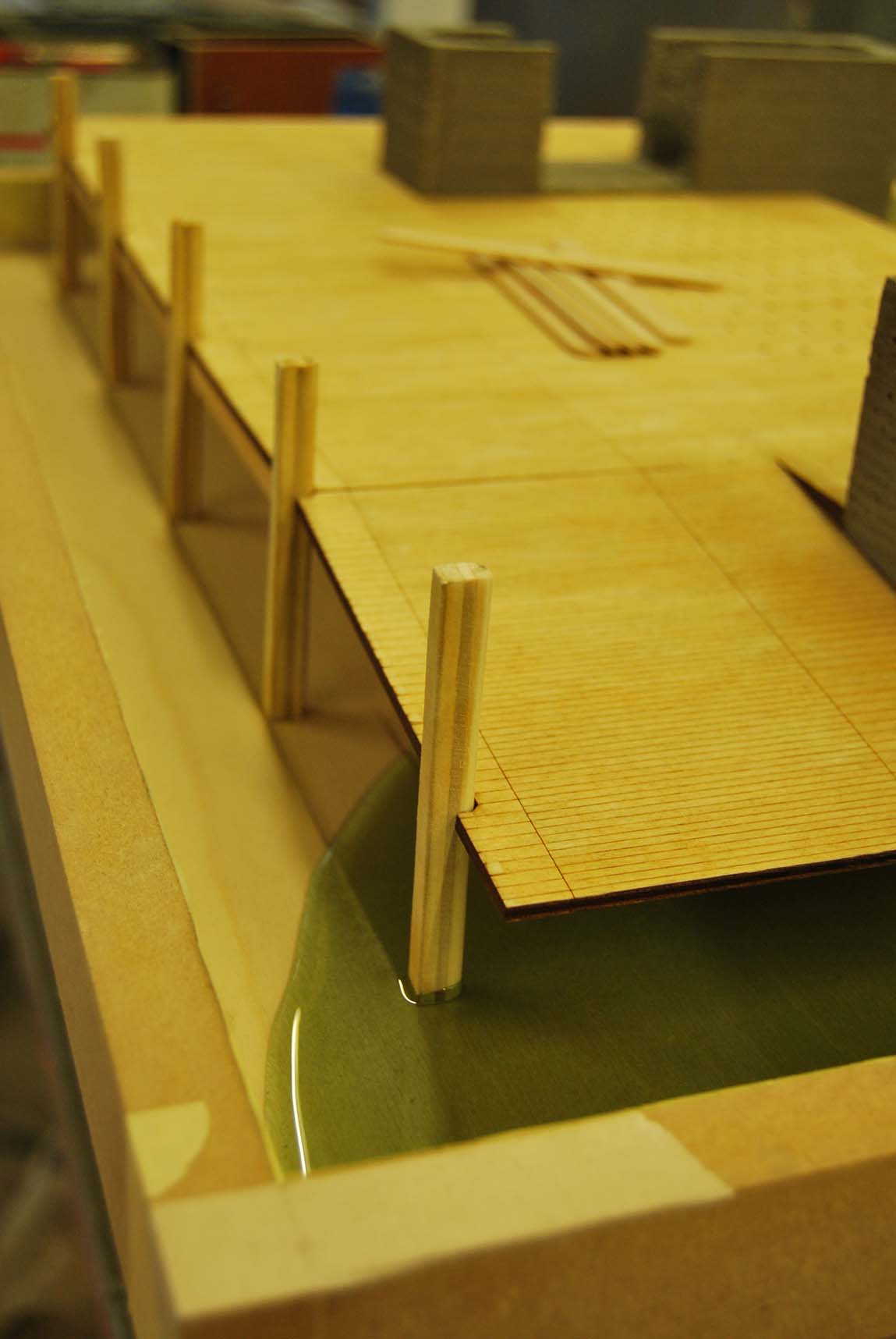
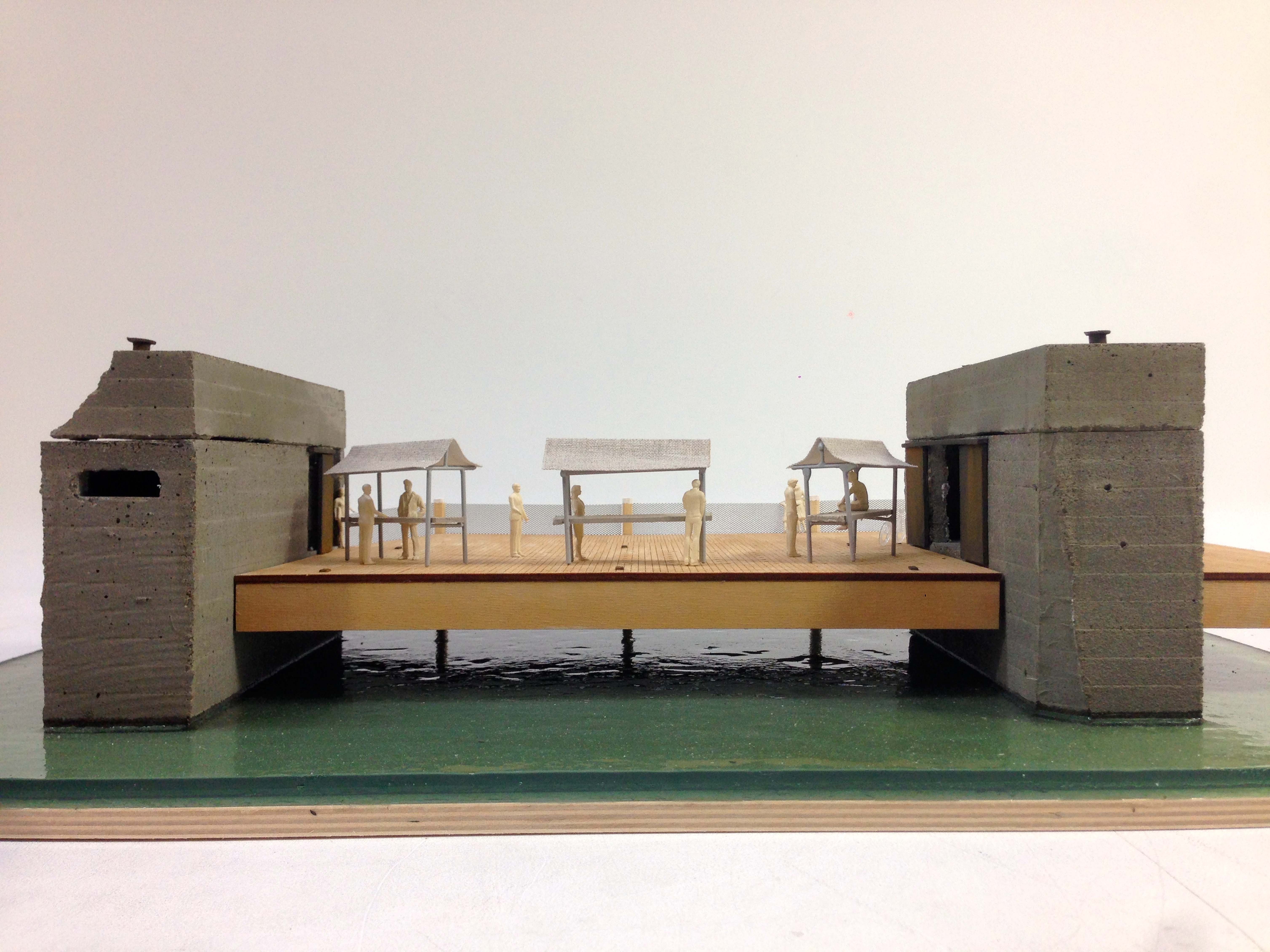
Due to the holistic approach to the design of the building it was important to show the complete building in a 1:200 scale model. One of the results aimed for with this project is to provoke in order to create discussion; how should architecture behave in times of ecological crisis? Thereby it will hopefully contribute to the architectural discourse. With this goal the model could contribute by seducing its viewers, therefor a certain level of expressive aesthetics needed to be achieved. At last the model functioned as constructional test. The gypsum 3d printed elements in the model compare with the 3d printed ‘Ferrock’ elements in the design. Even so the lattice beam construction functions with an actual pressure ring in the model. No glue is used and therefor resembles how it will work in reality.

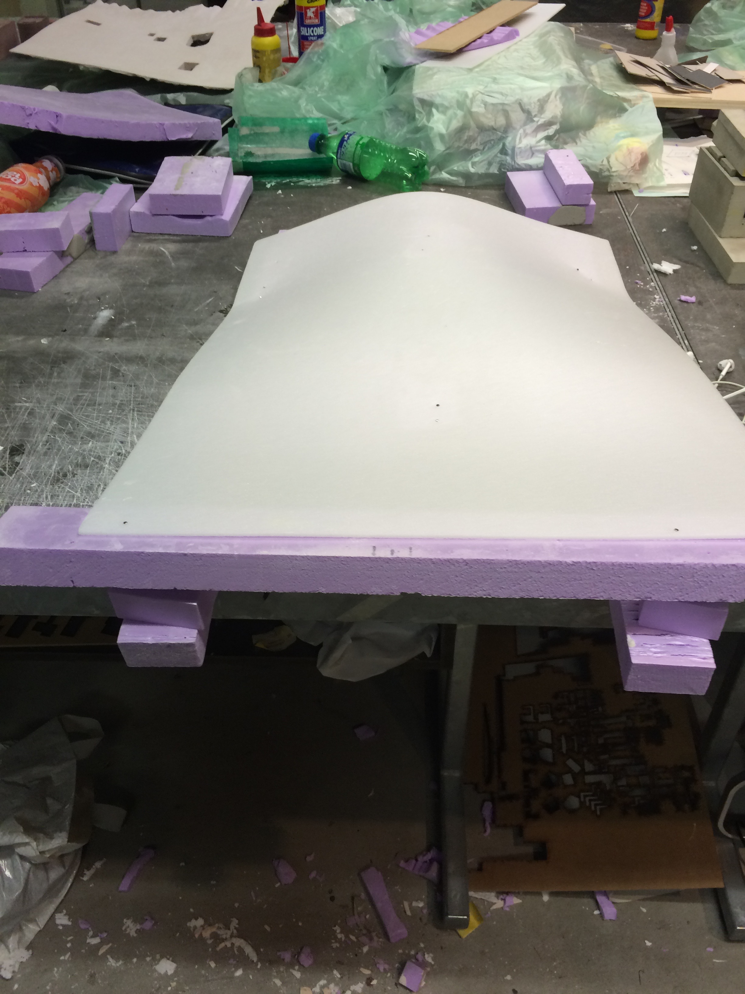
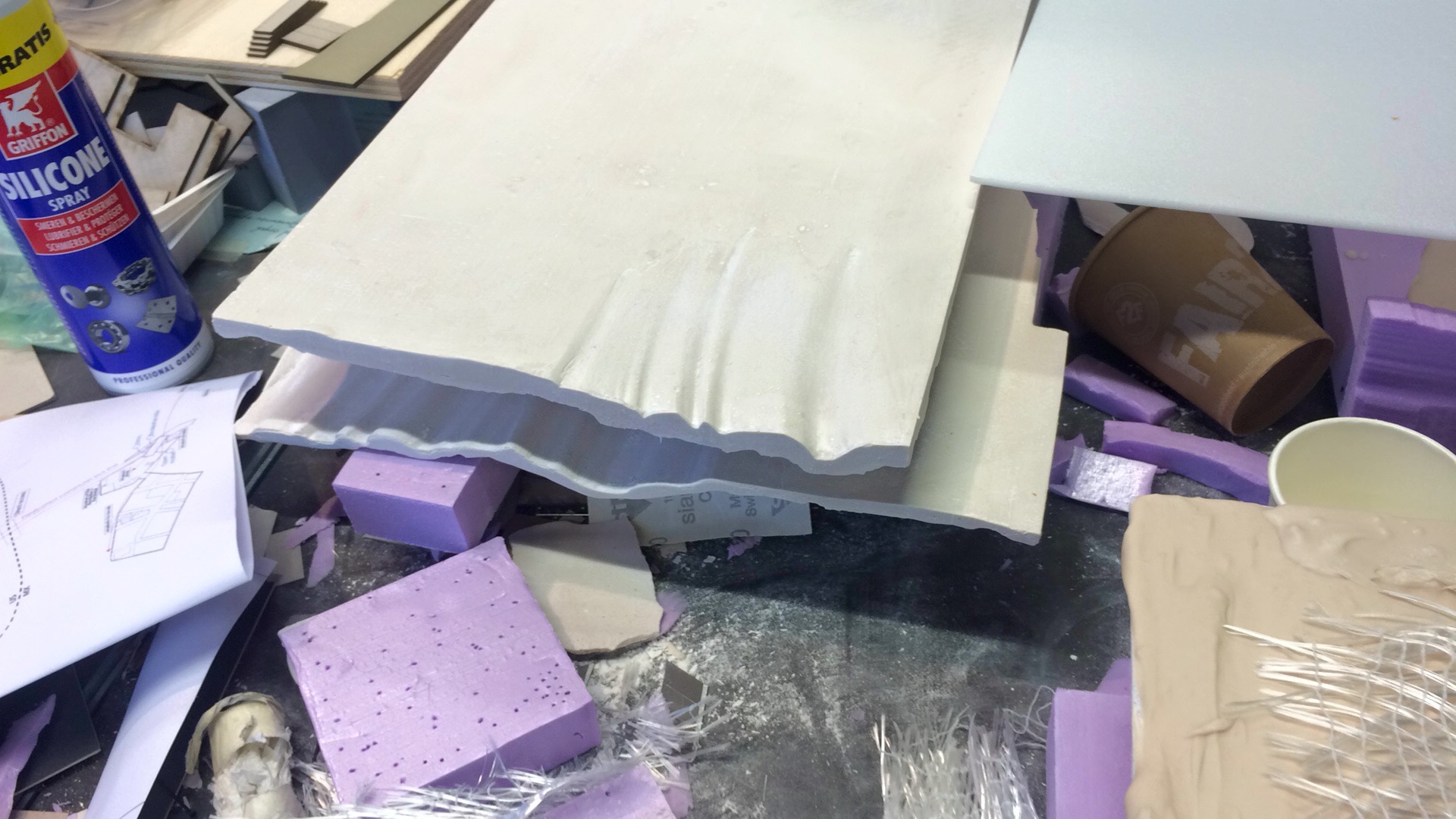
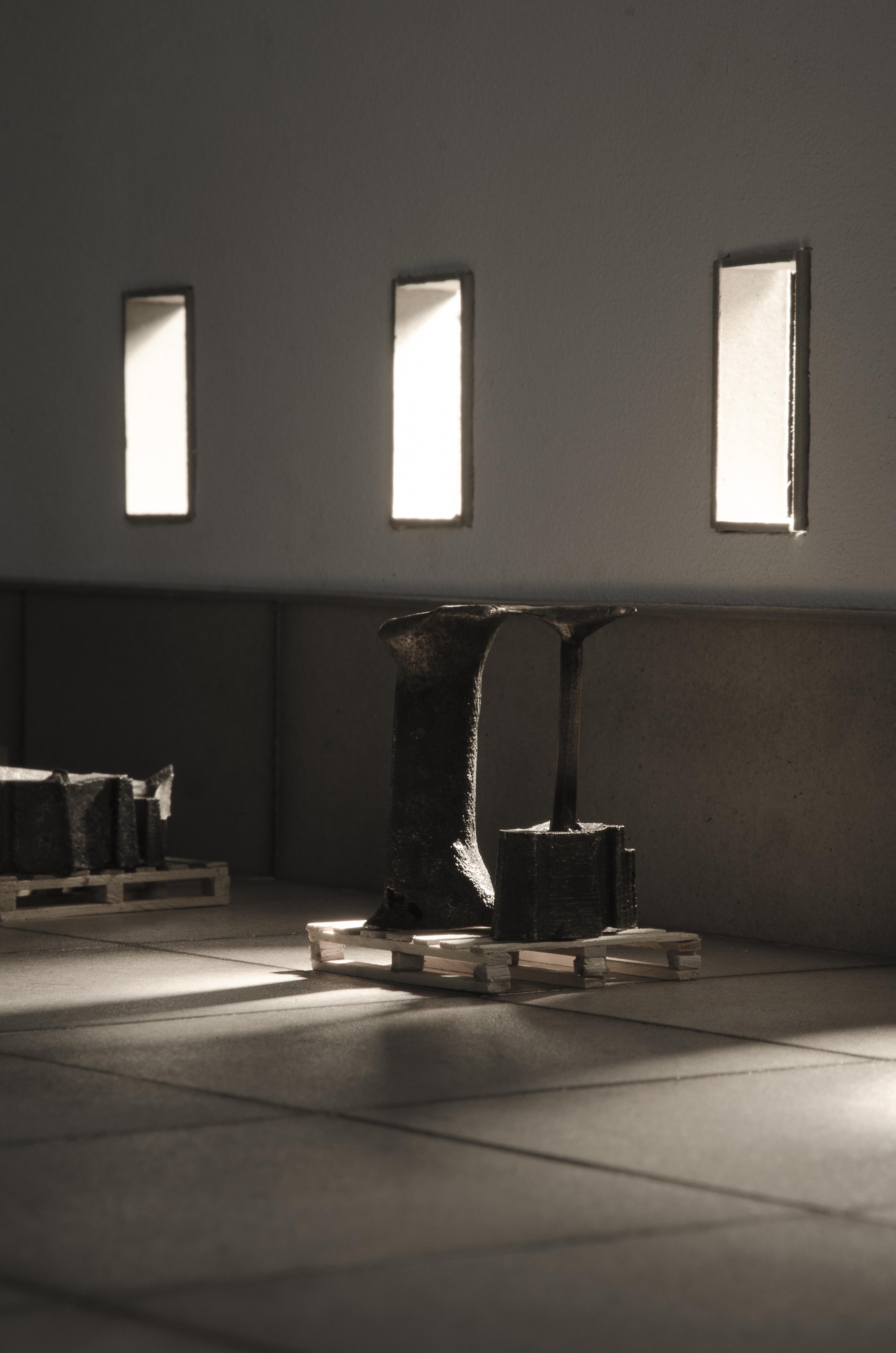
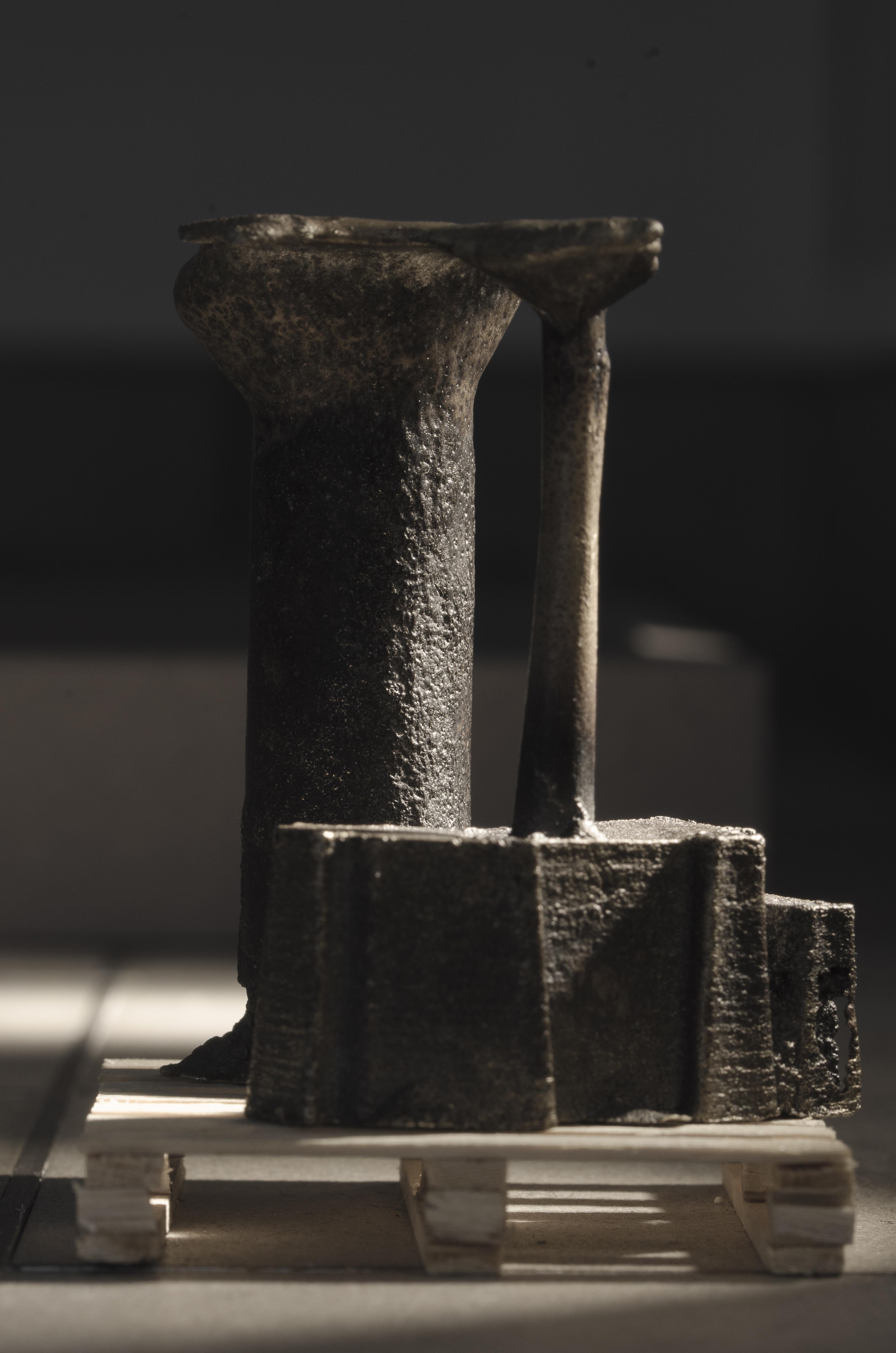
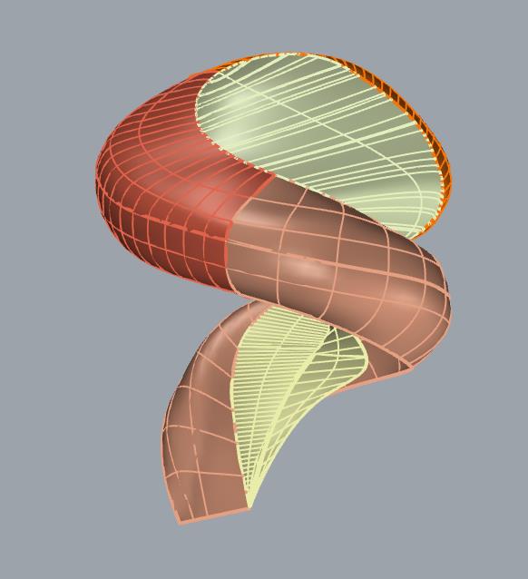
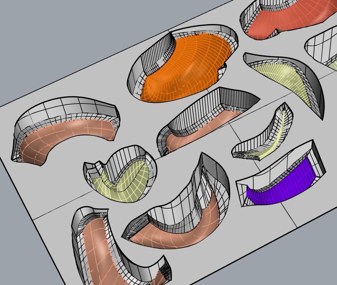
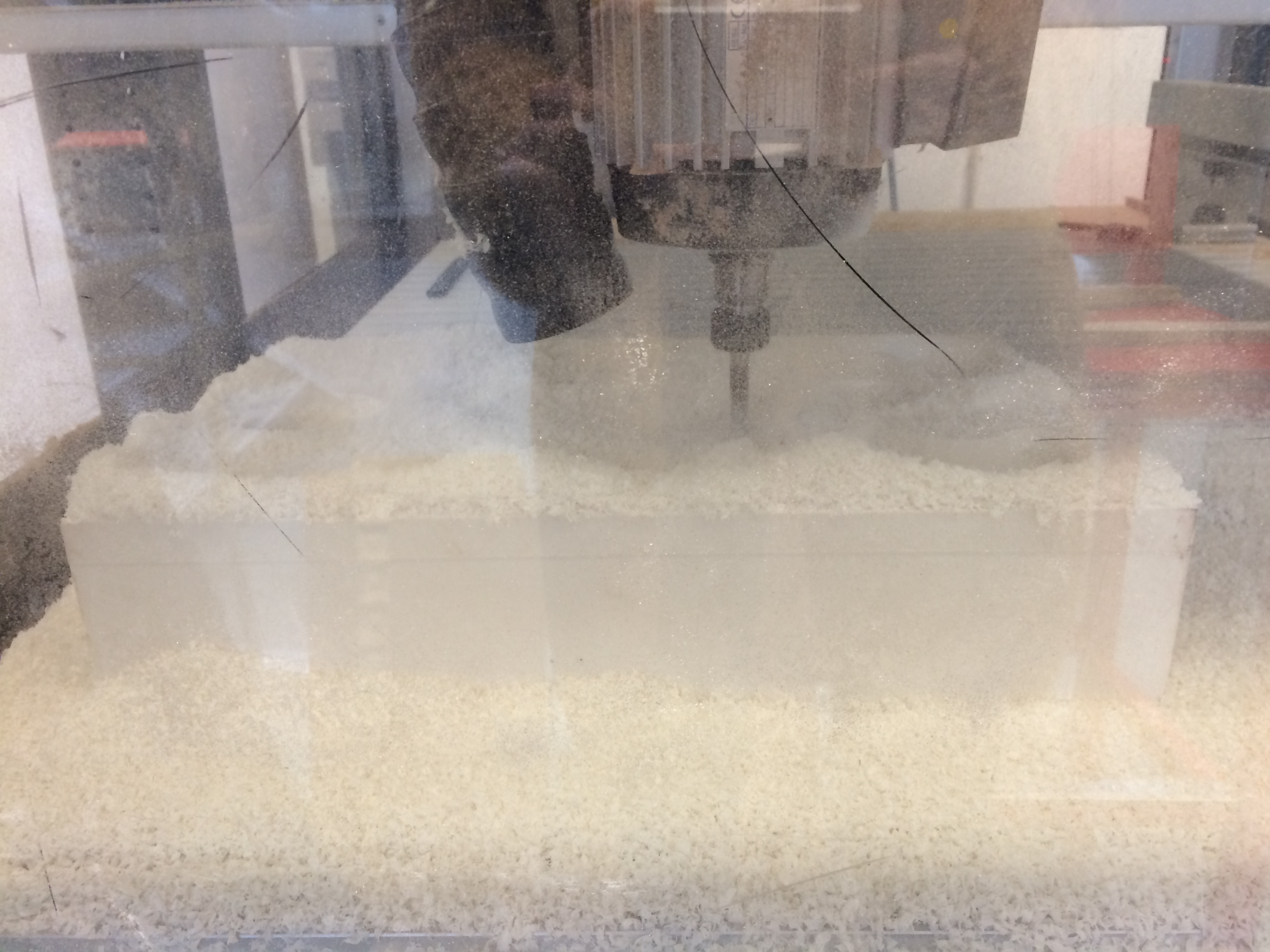
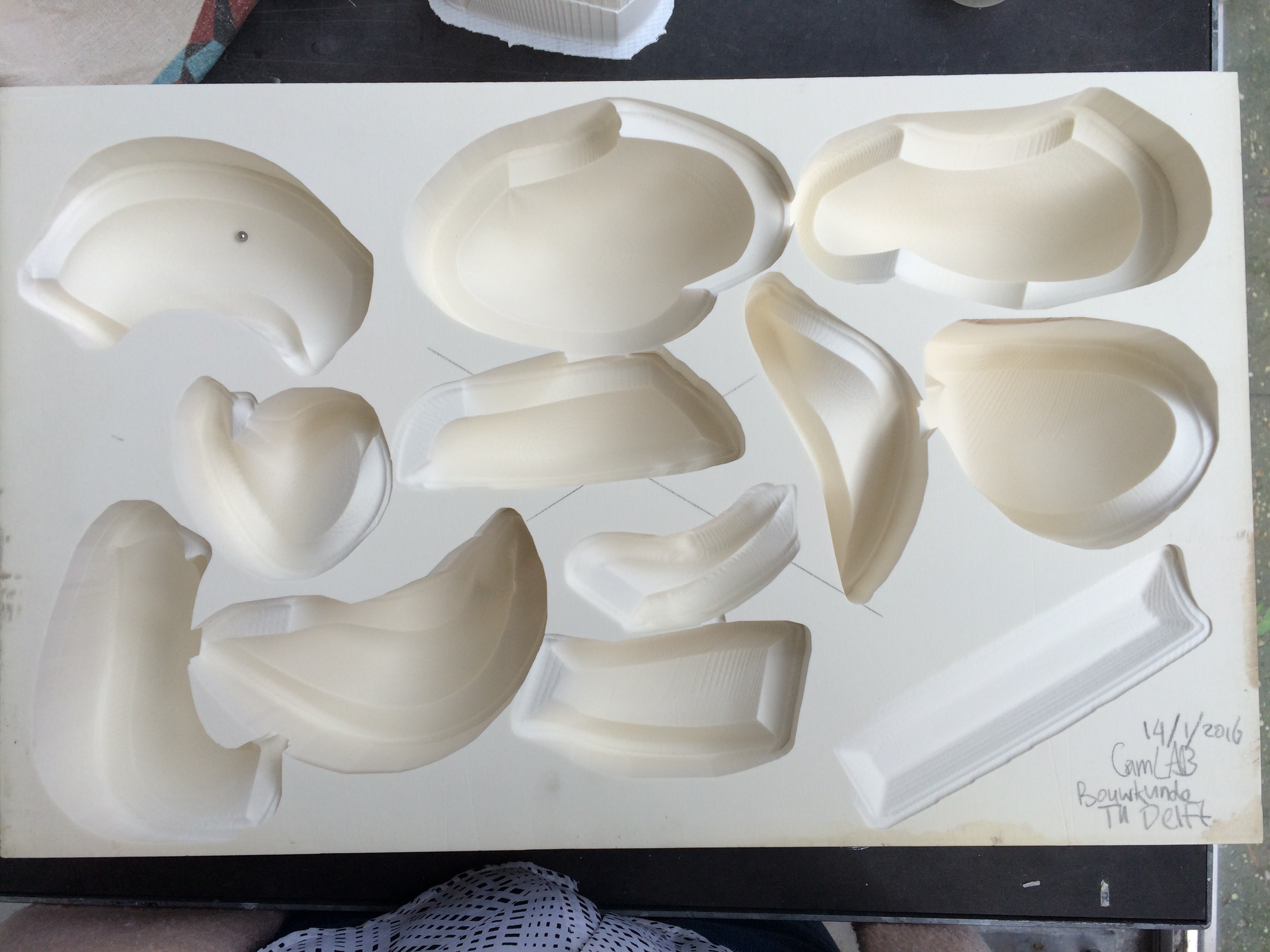
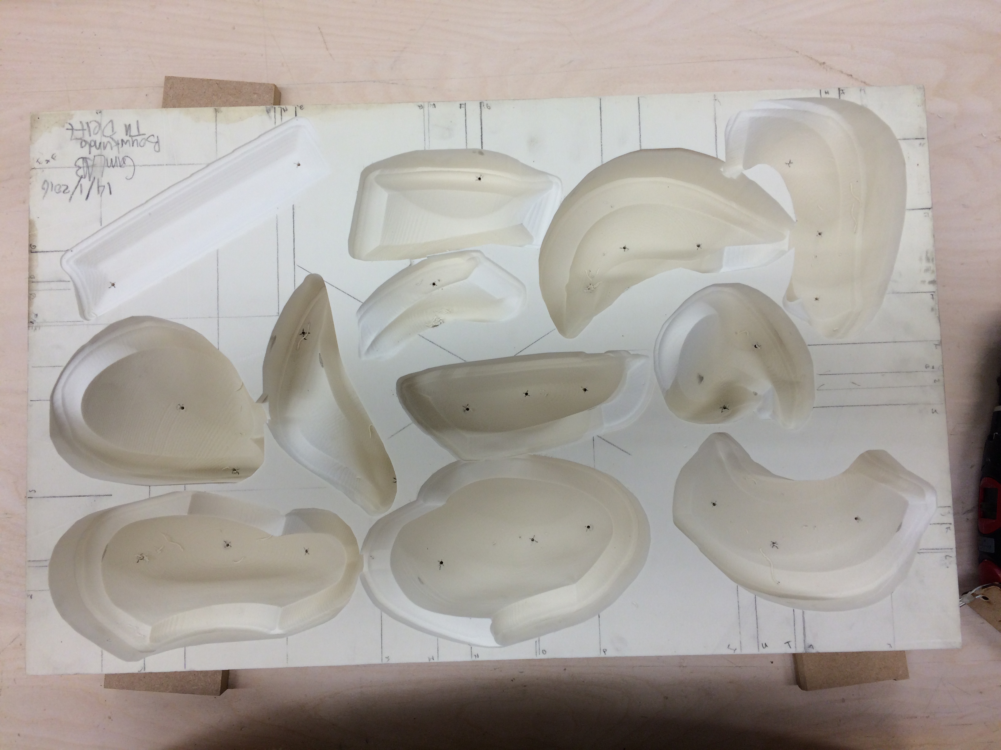
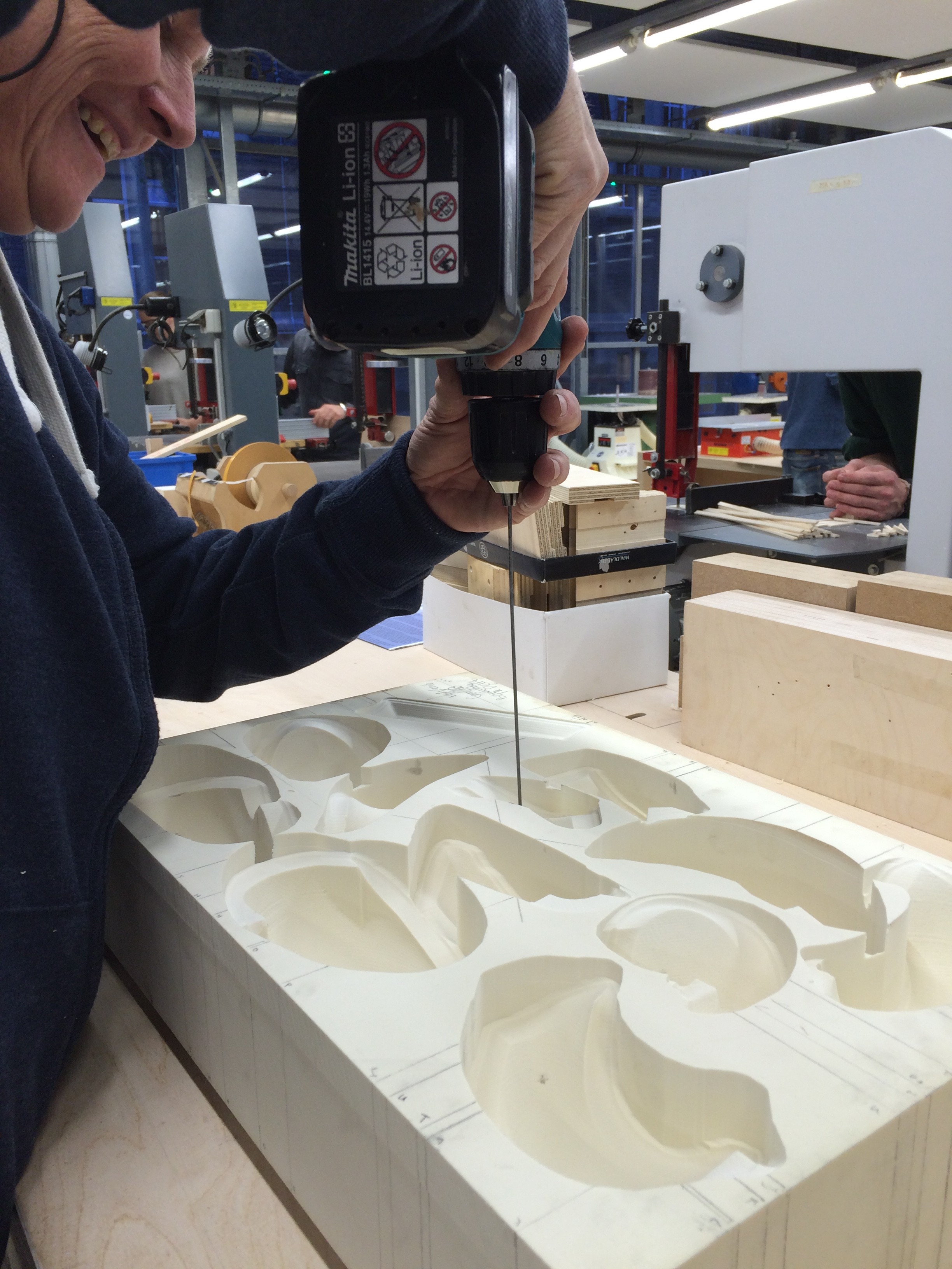
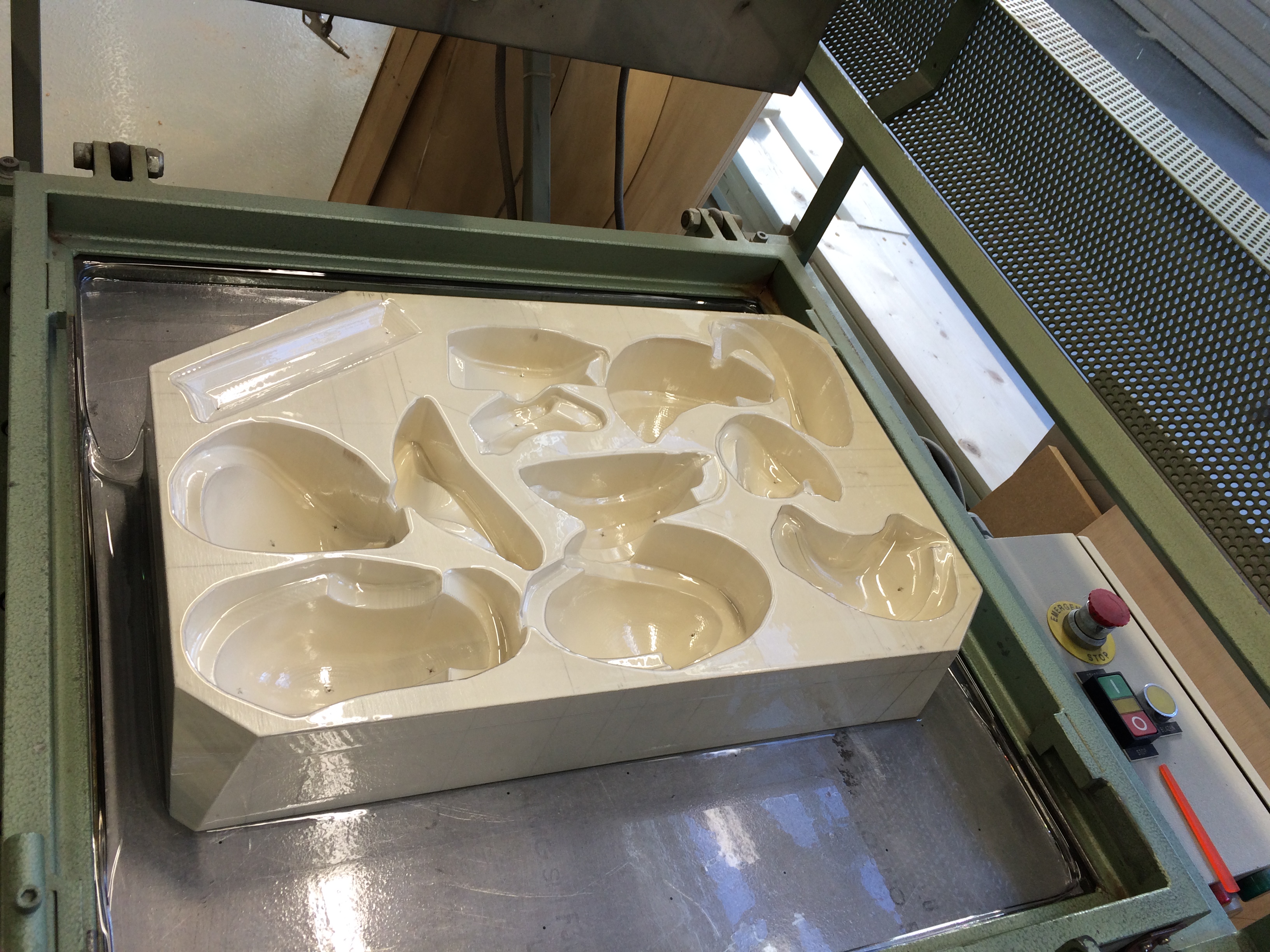
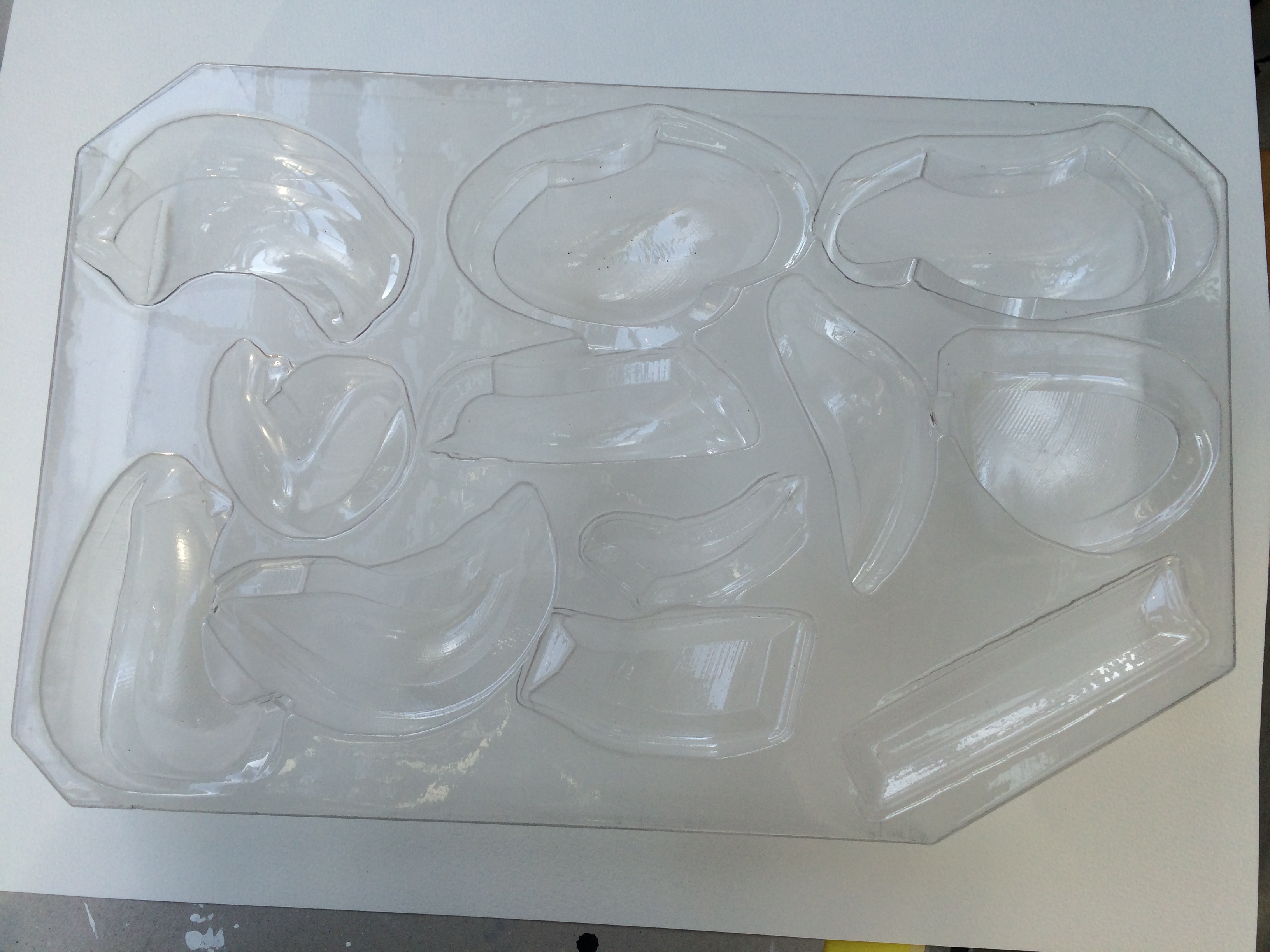
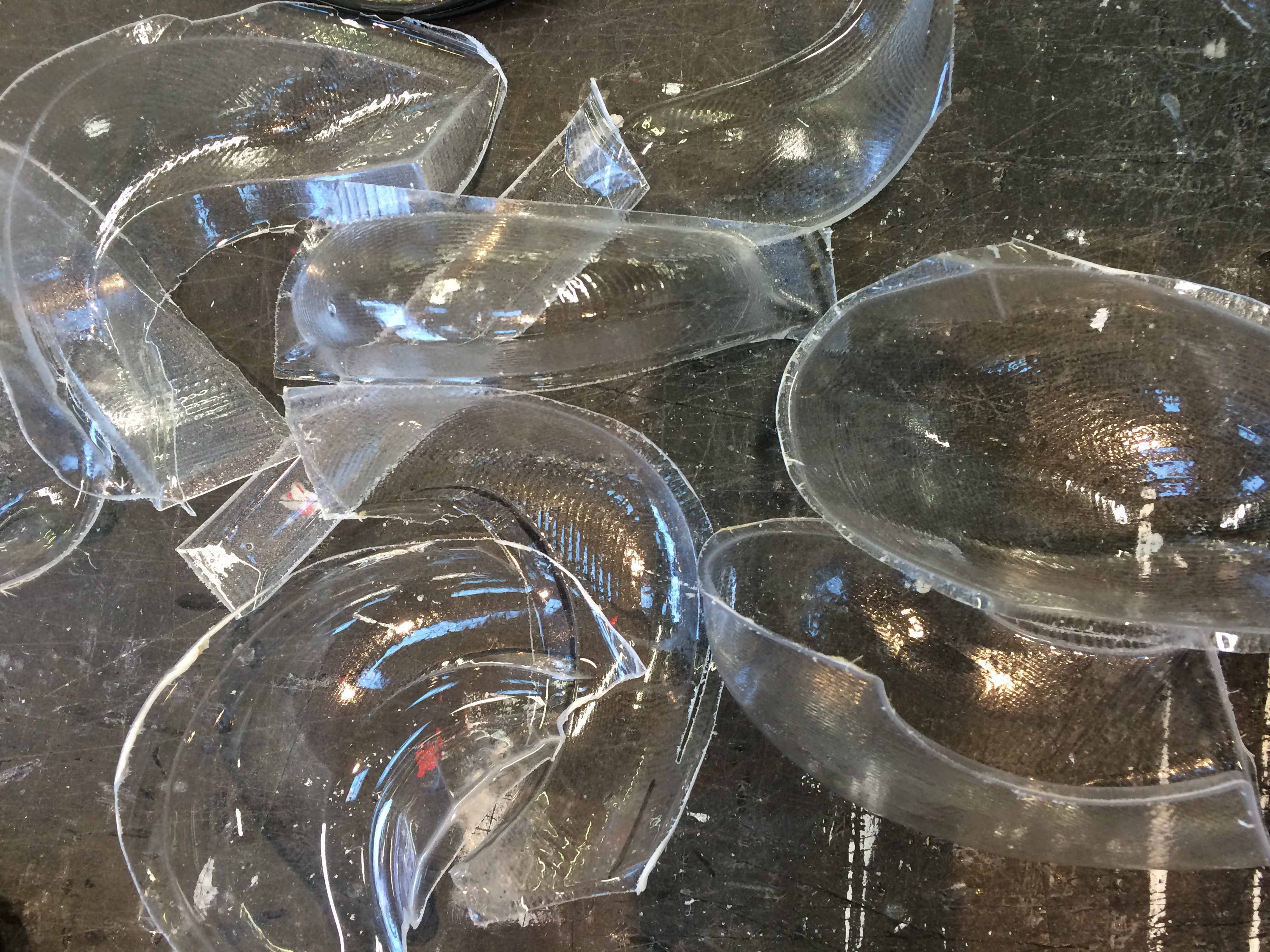
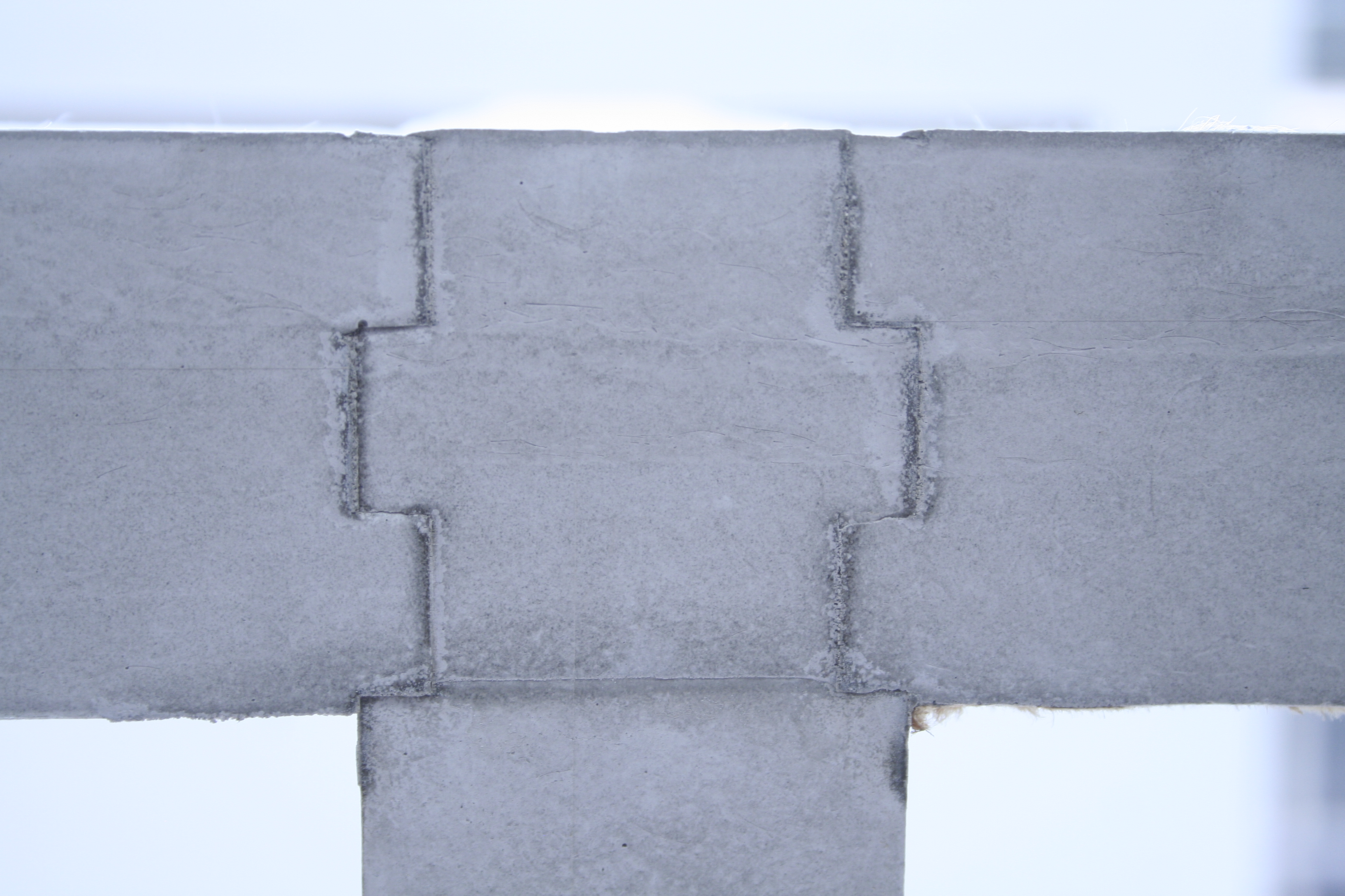
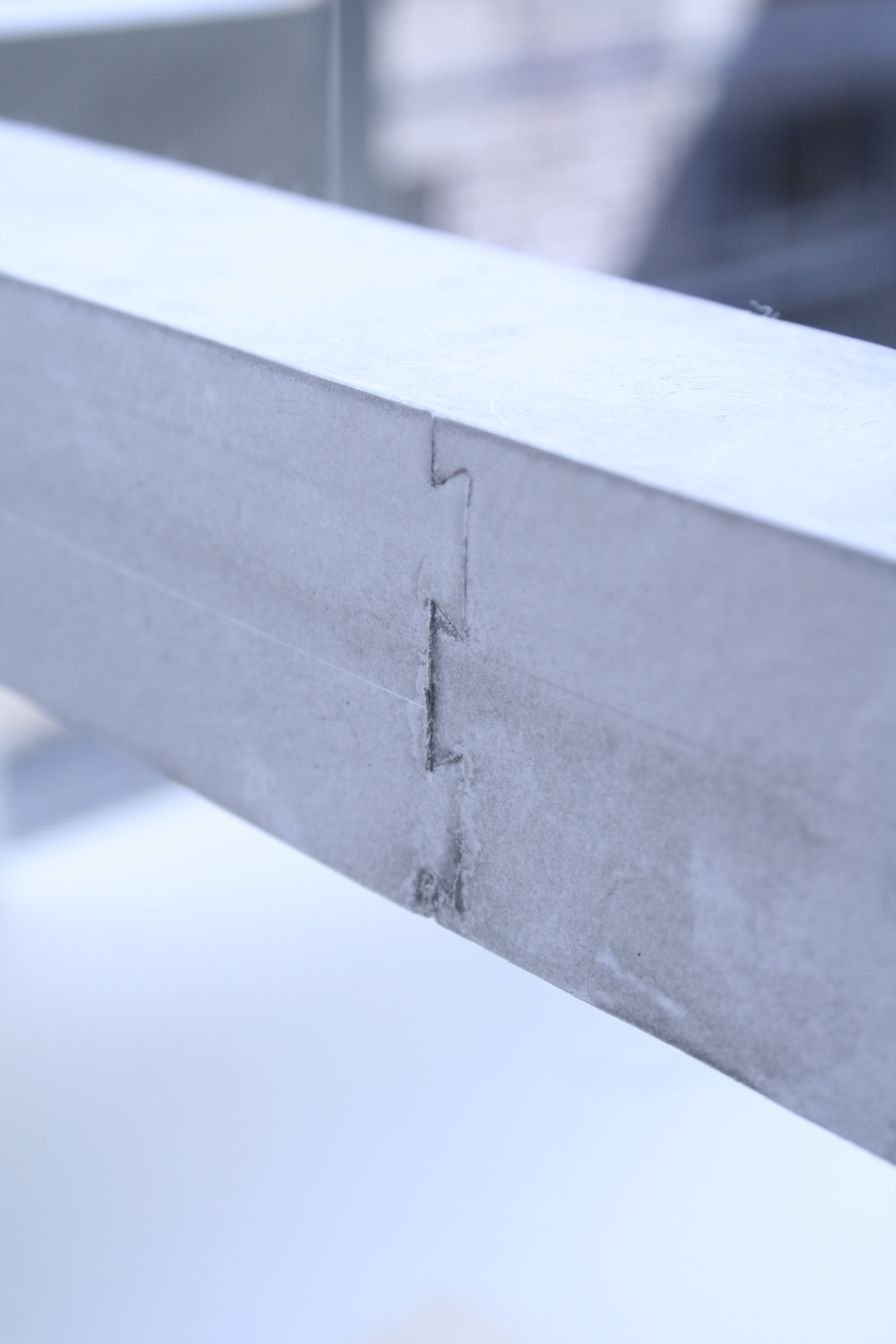
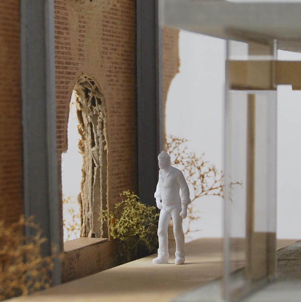
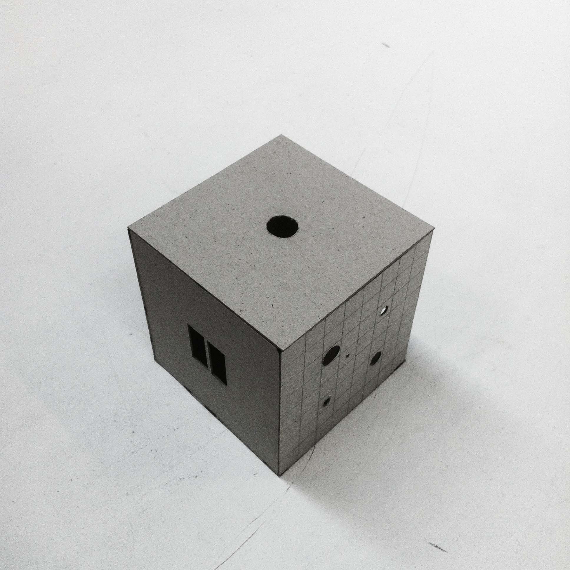
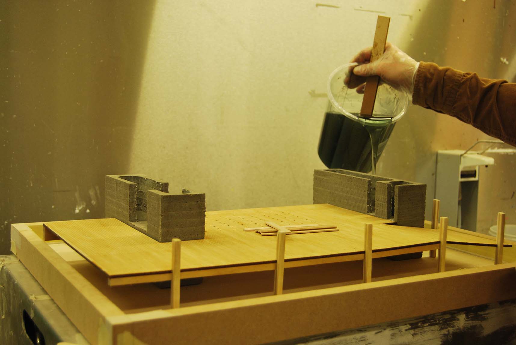
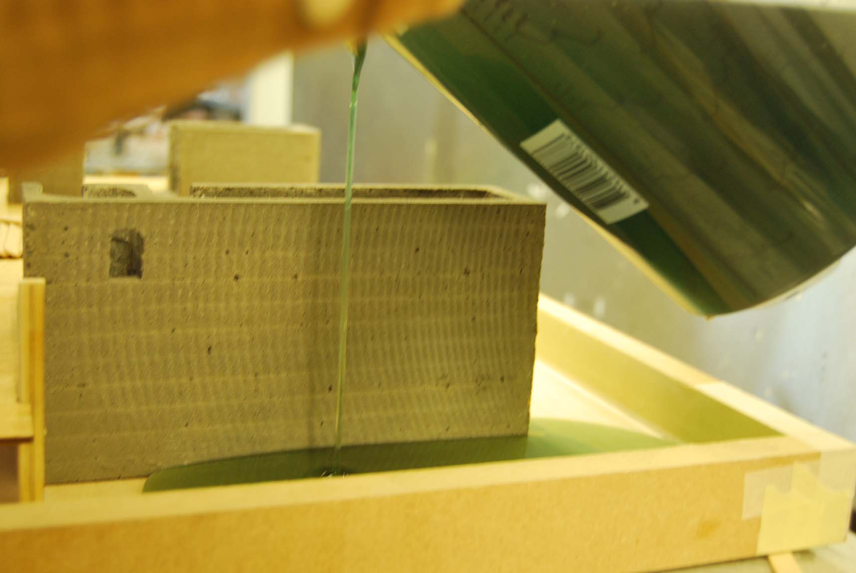
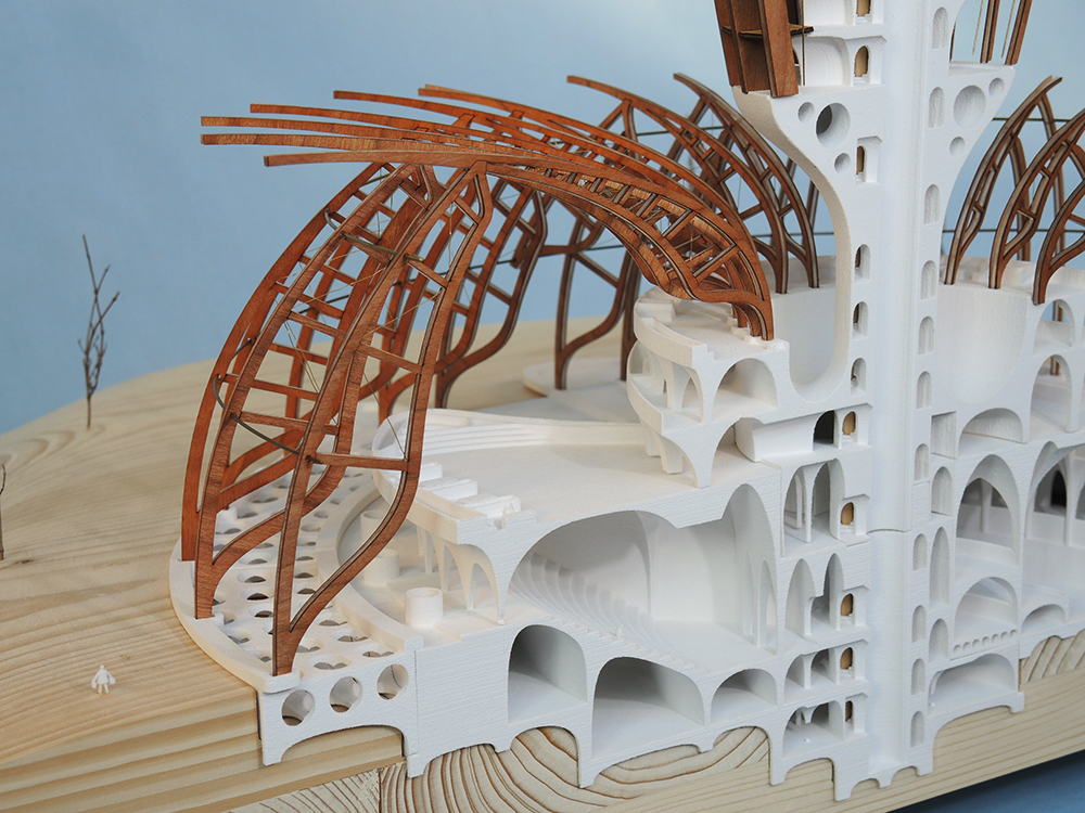
A big question in the whole process was how to make the model of such an extraordinary design. The double curved geometry with these small sizes where only able to construct by 3d printing. I chose for the gypsum printer, because it is so refined and thereby has a beautiful appearance. Also it prints faster than the plastic printer. On the other hand it is expensive, fragile and time consuming to dig out the prints. The printer lays layers of powder and with a laser solidifies the volumes. When the machine is finished there is a block of powder with the solid piece inside. One really has to dig the print out and clean it as an archaeologist. After it’s cleaned a hardening spray can finish the printed elements in order to gain strength. A couple of layers can be applied, not too much, in order to keep the pleasing texture of the gypsum.

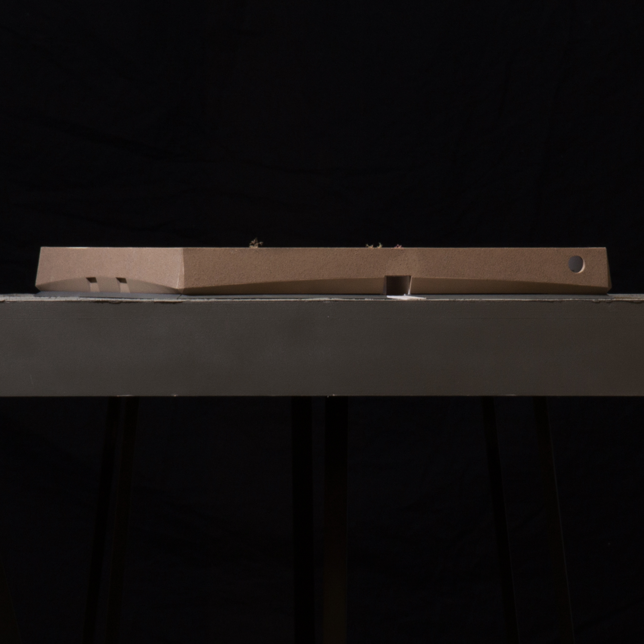
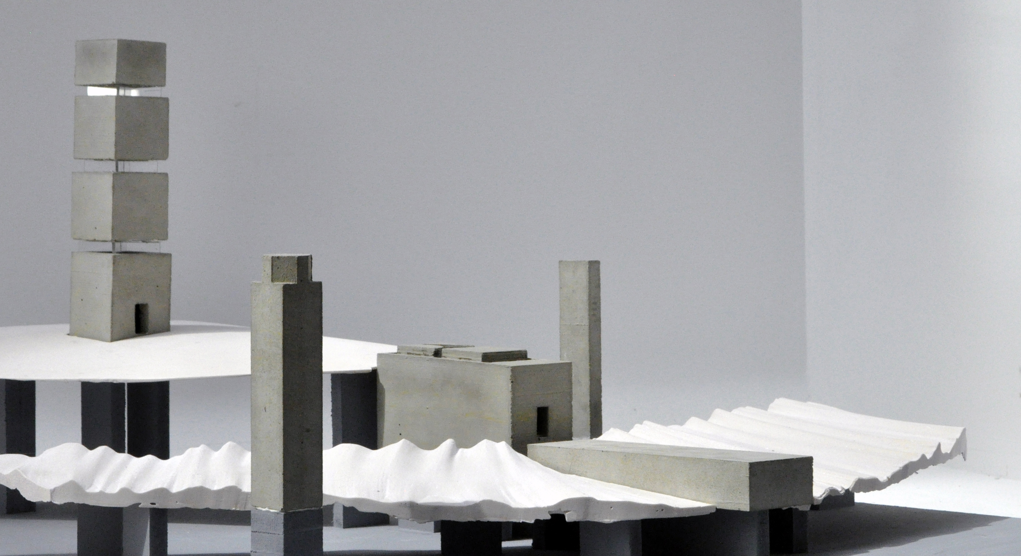
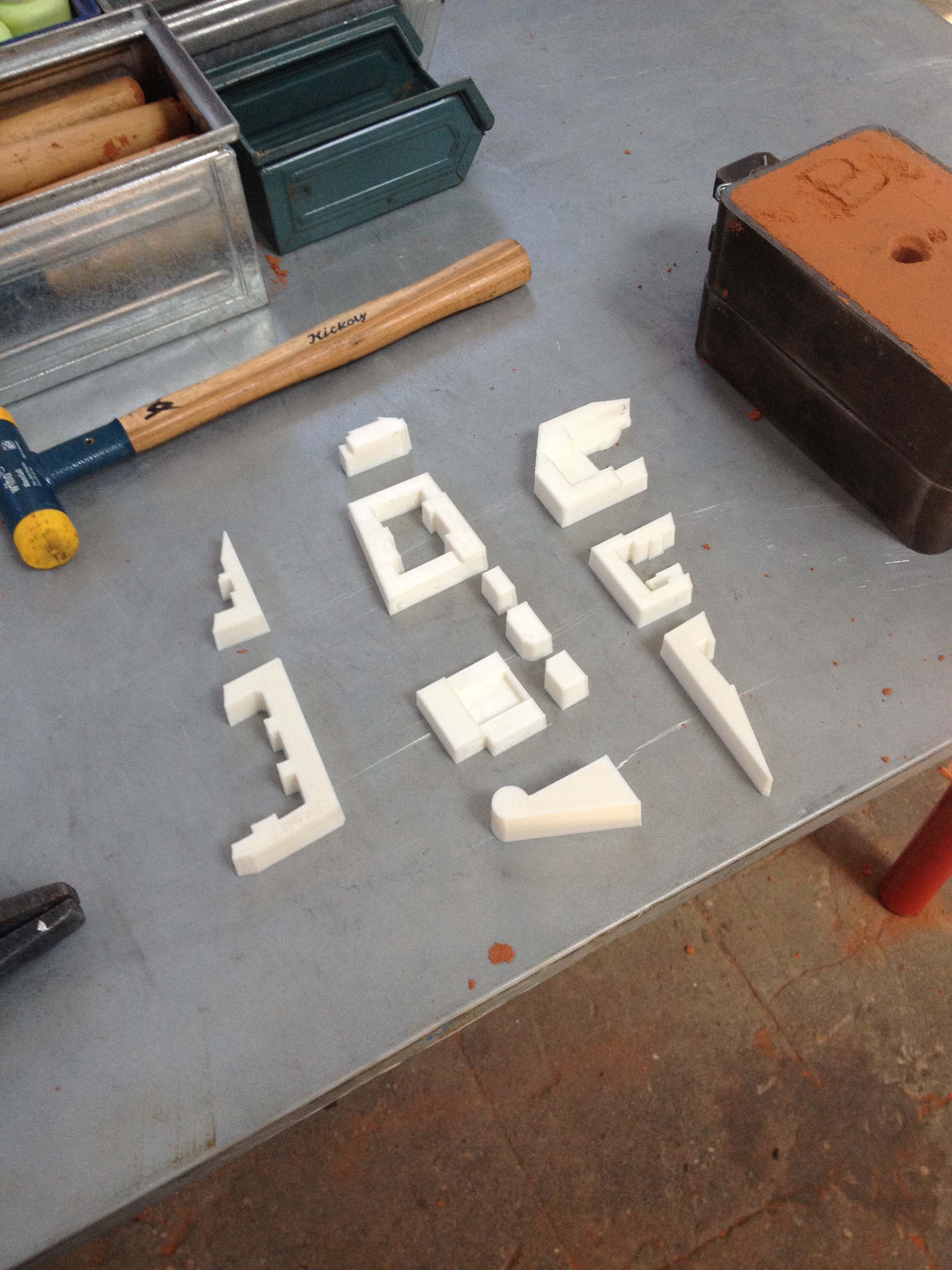
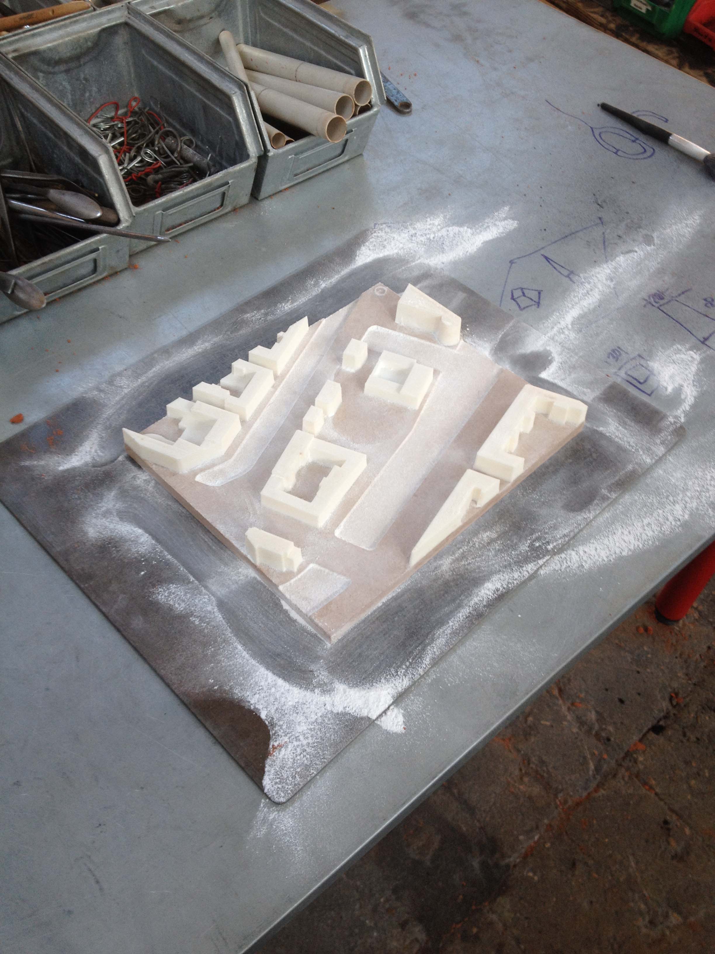
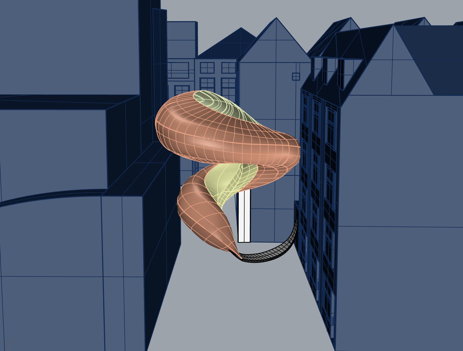
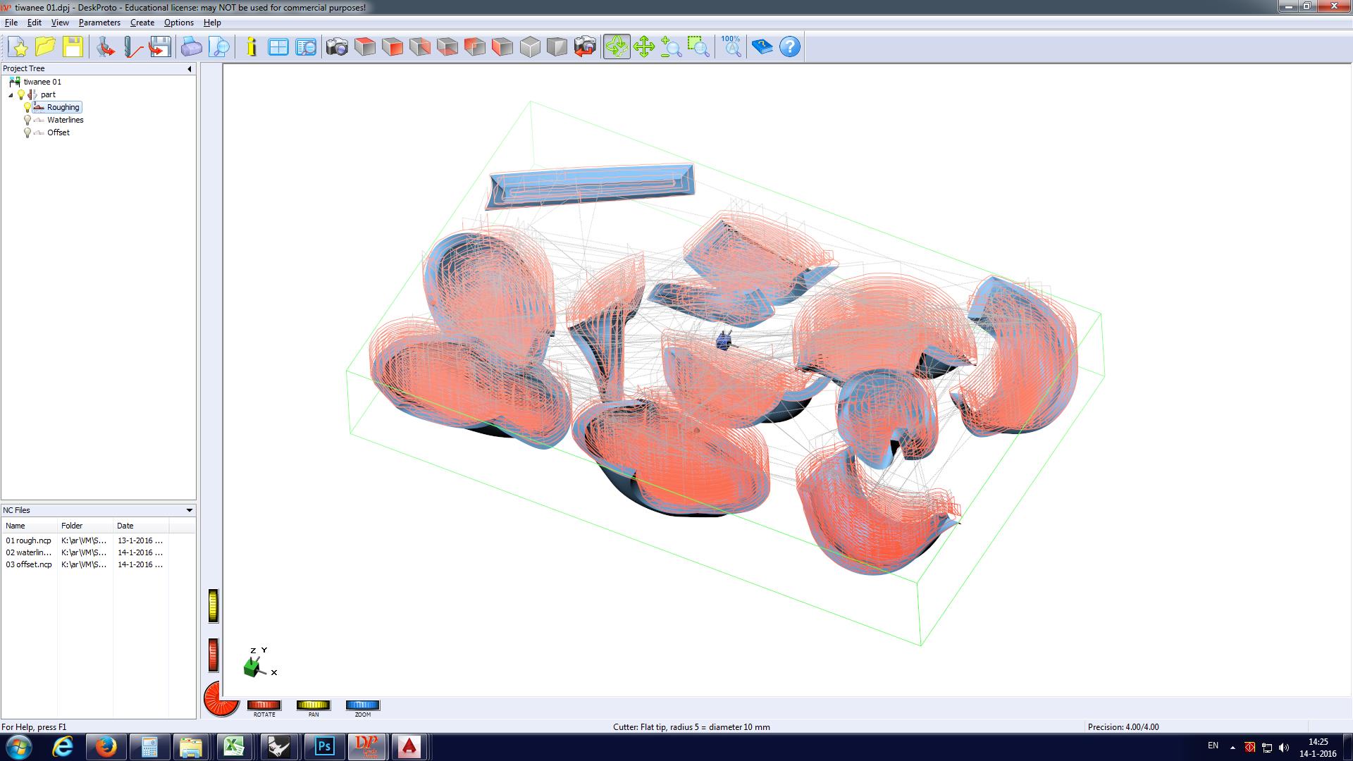
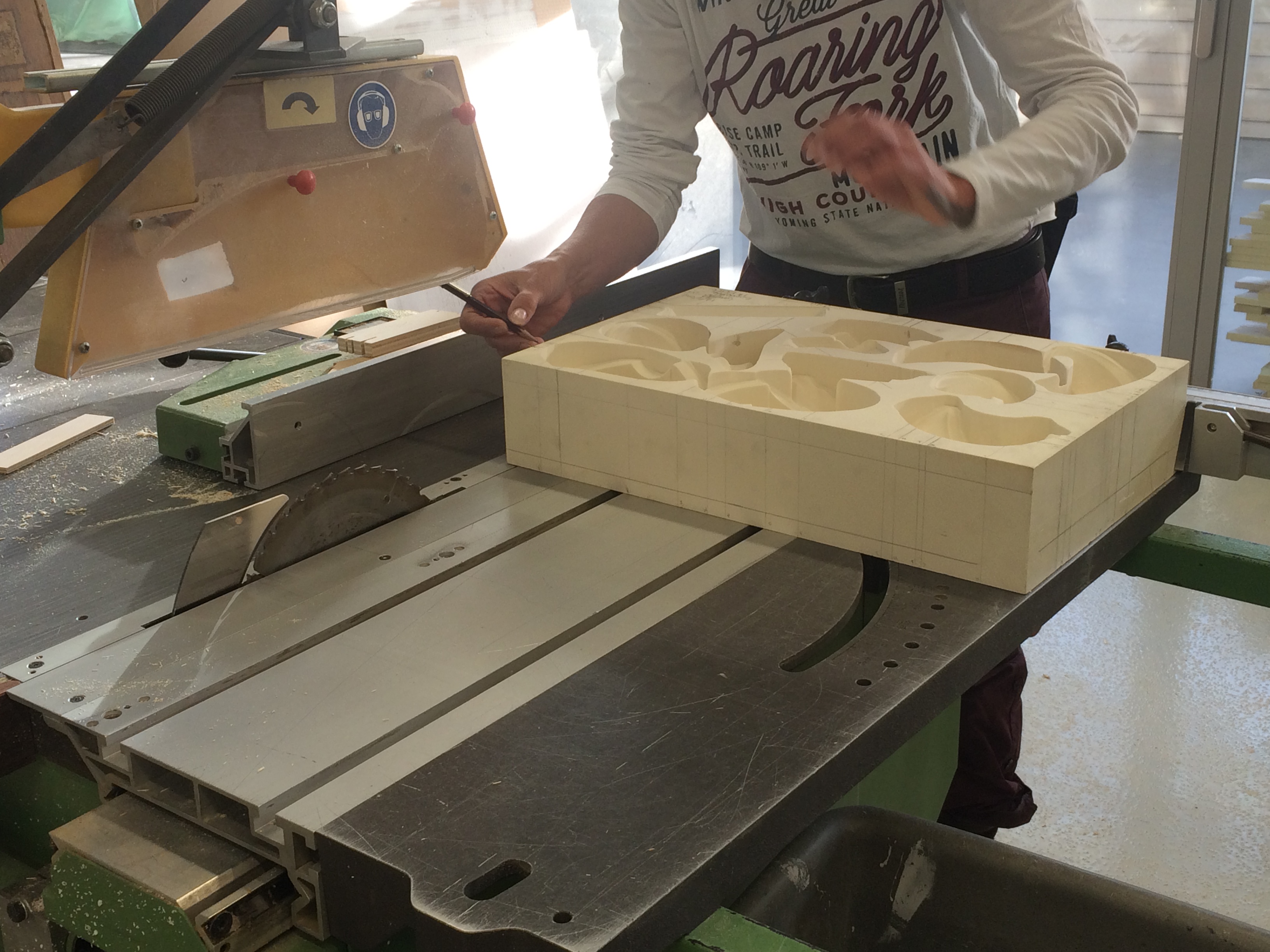
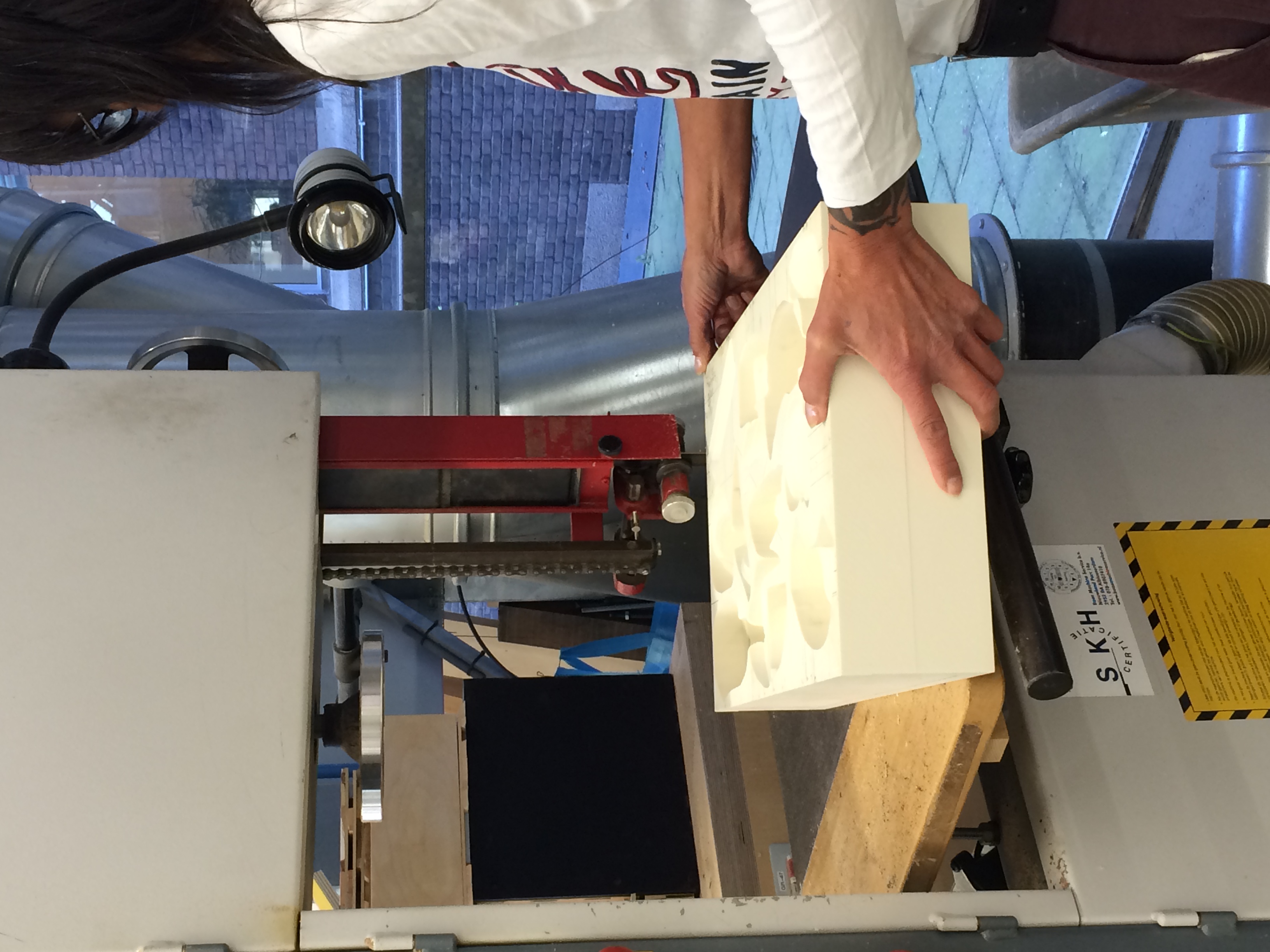
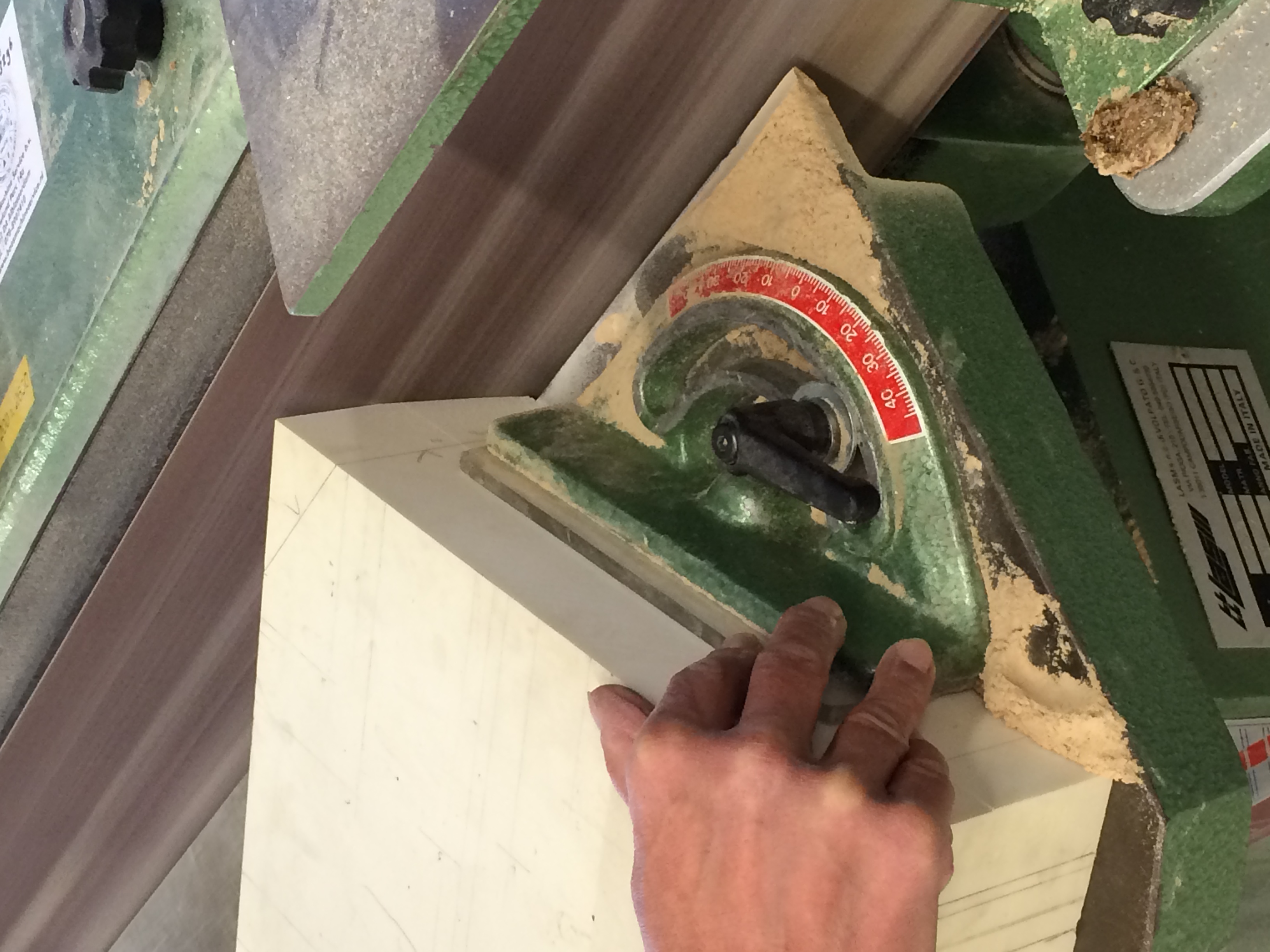
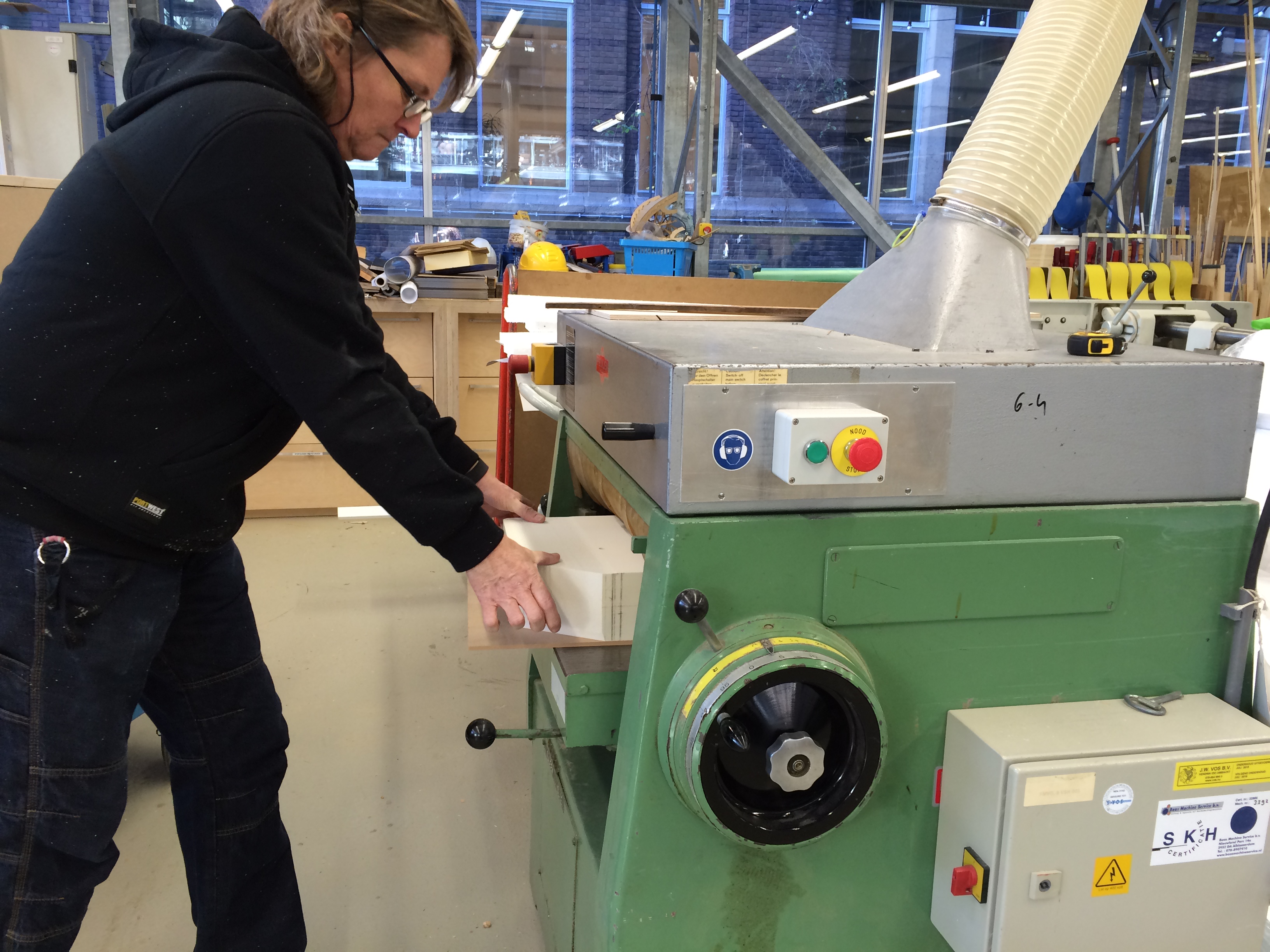
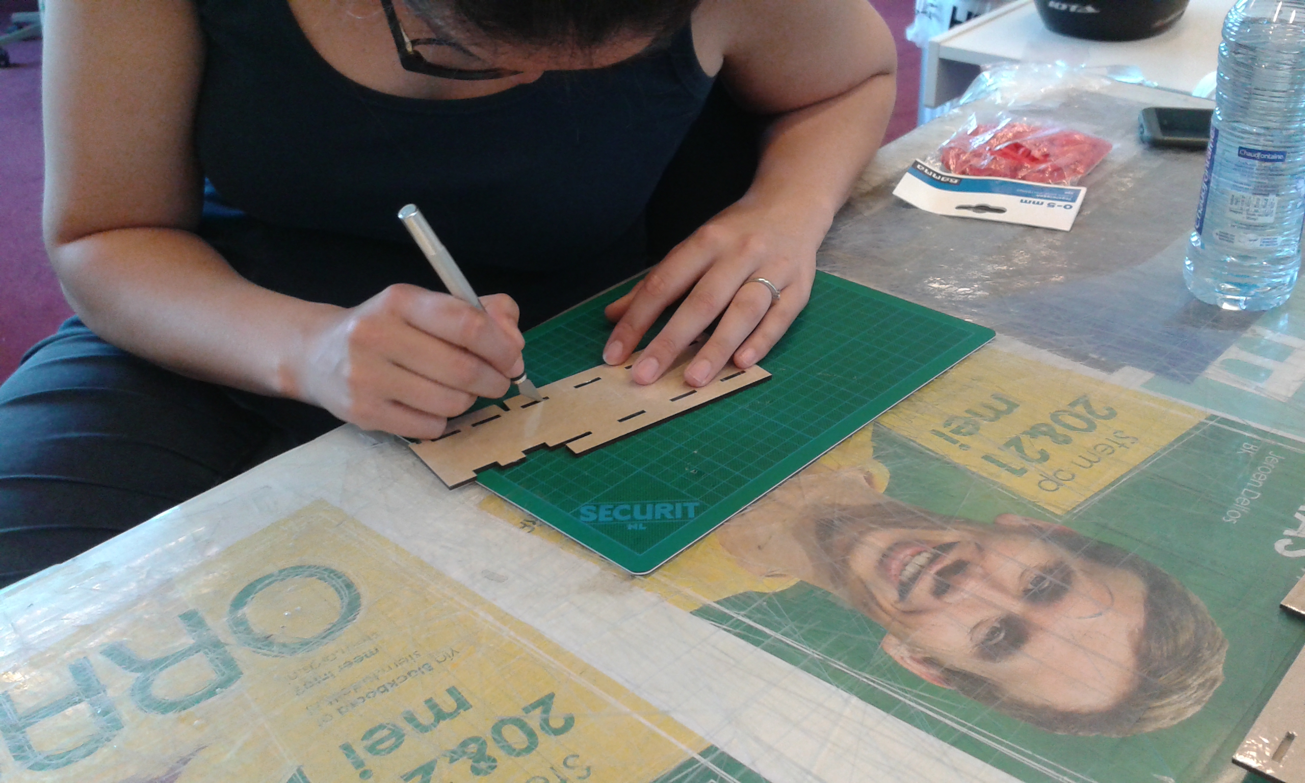
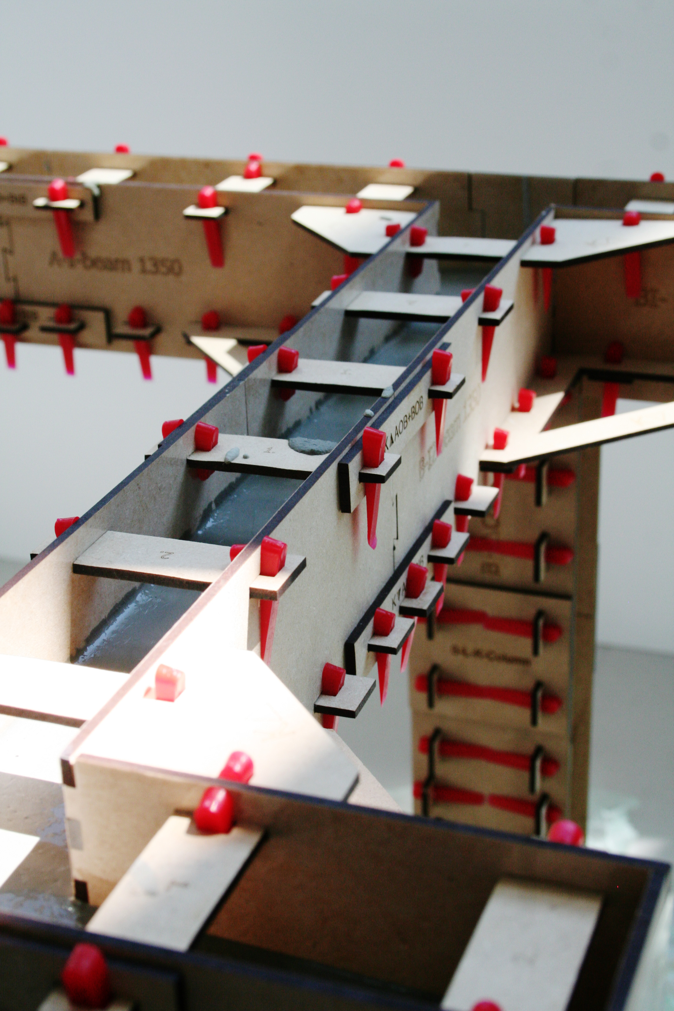
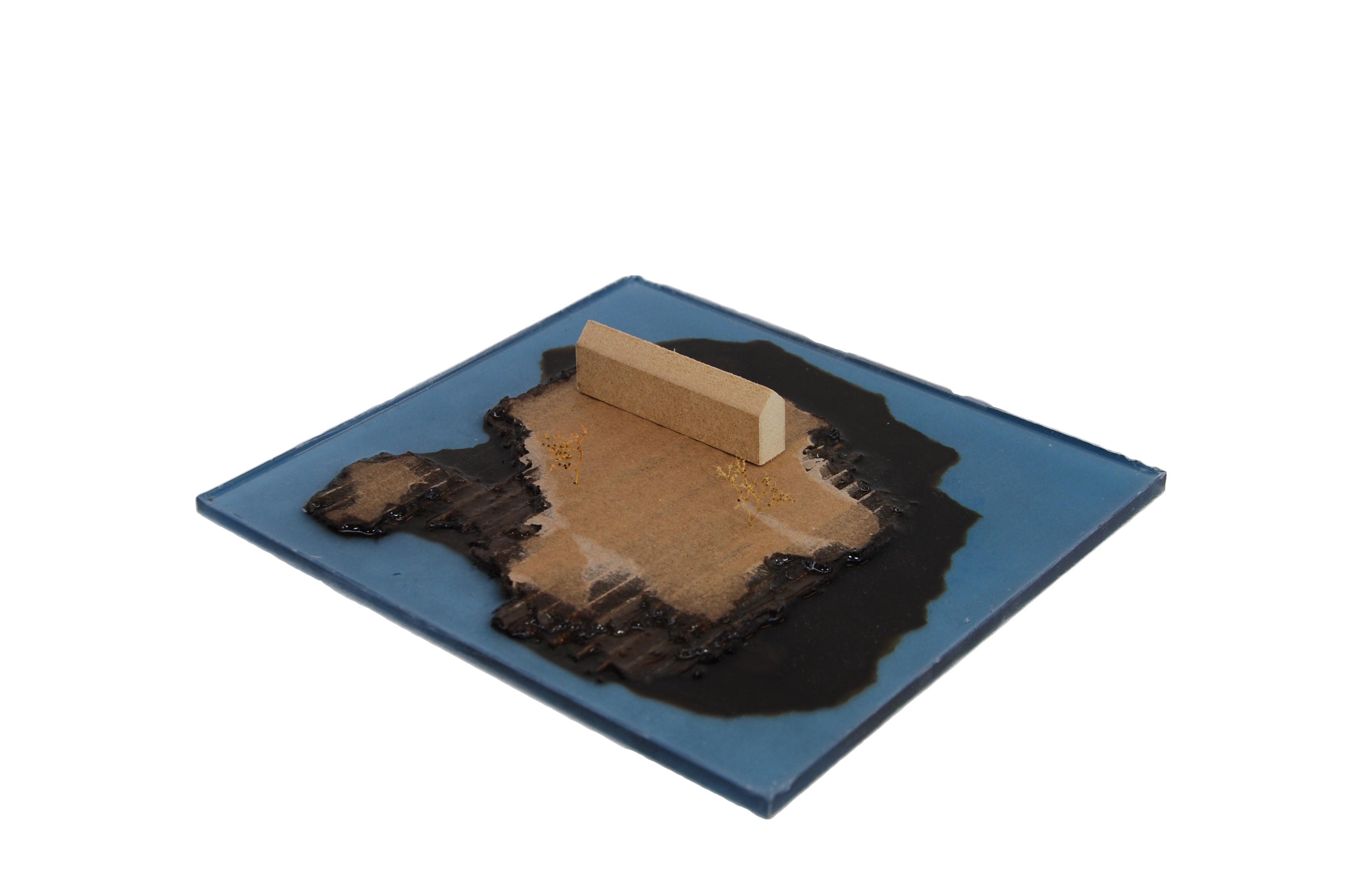
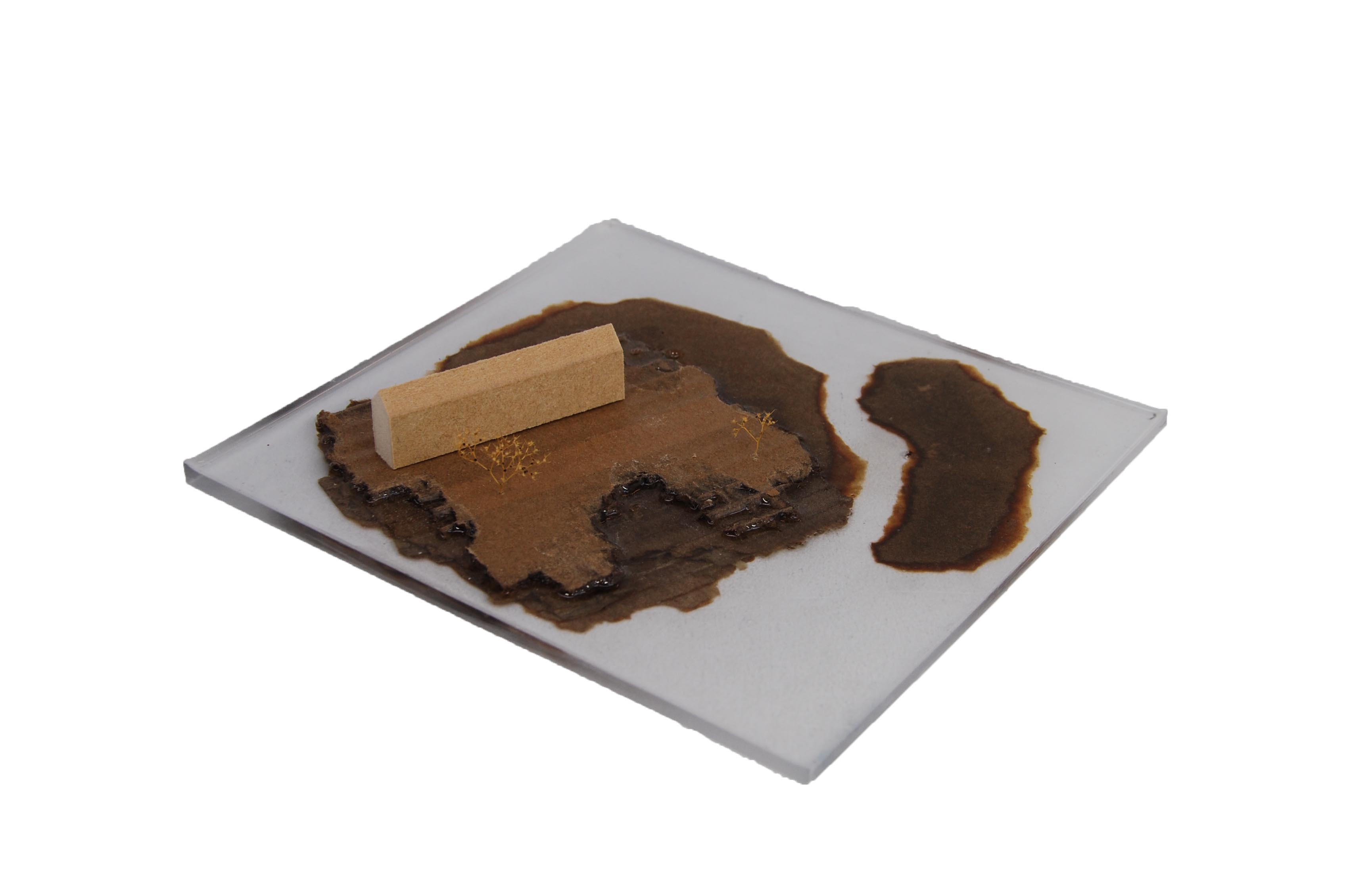
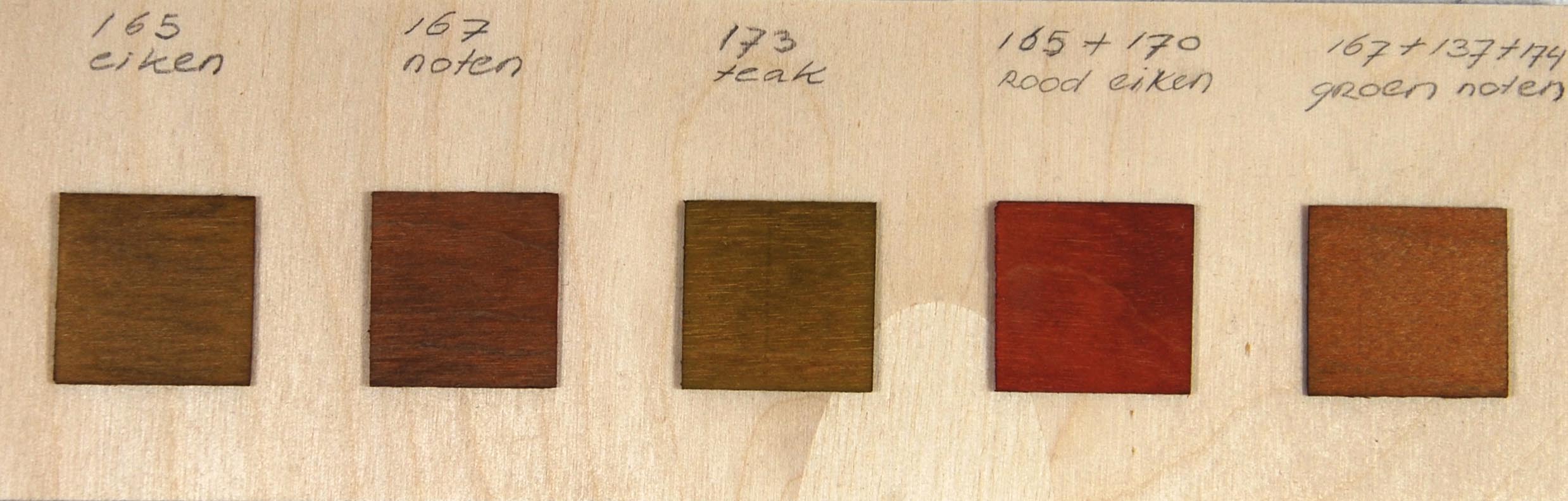
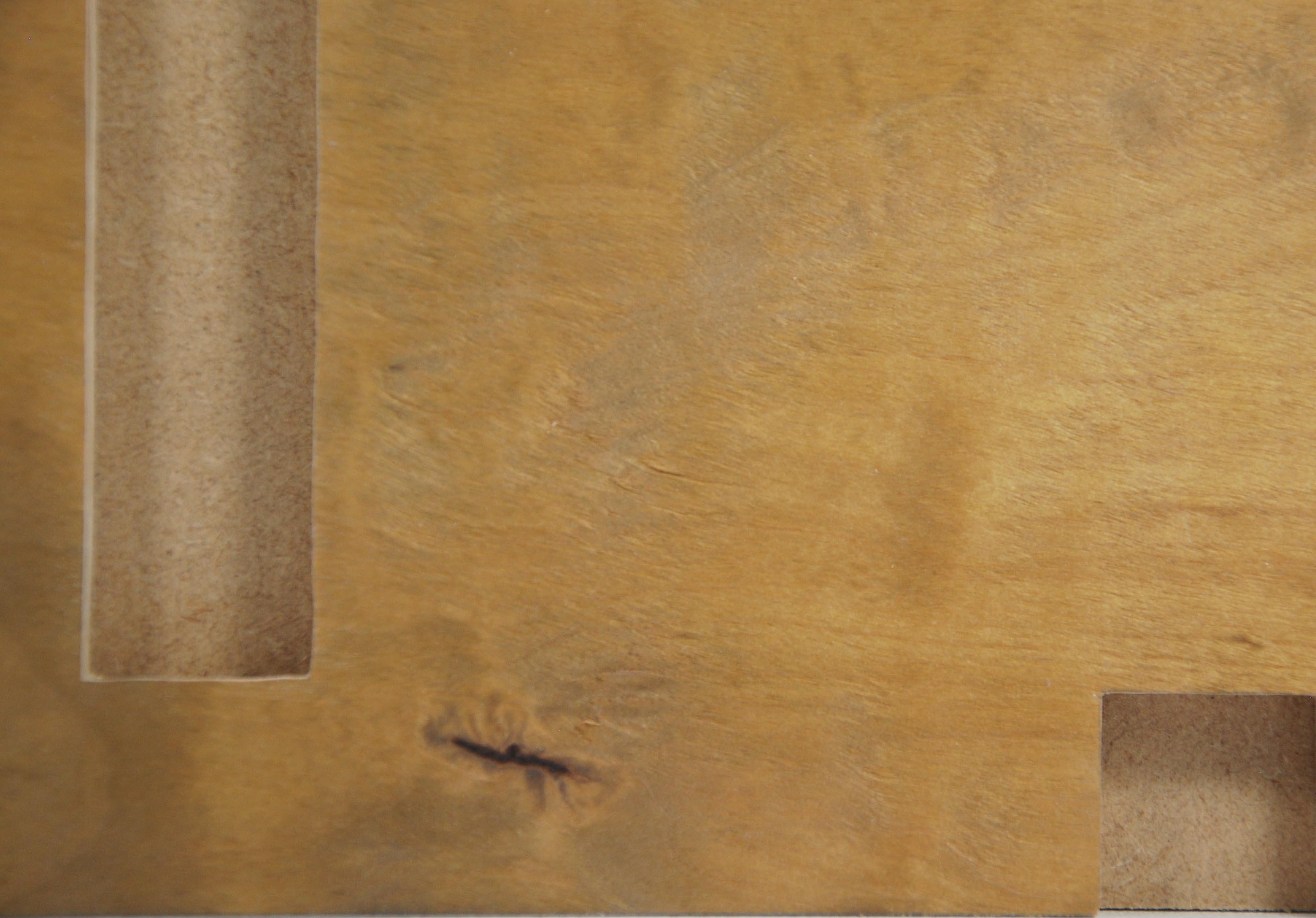
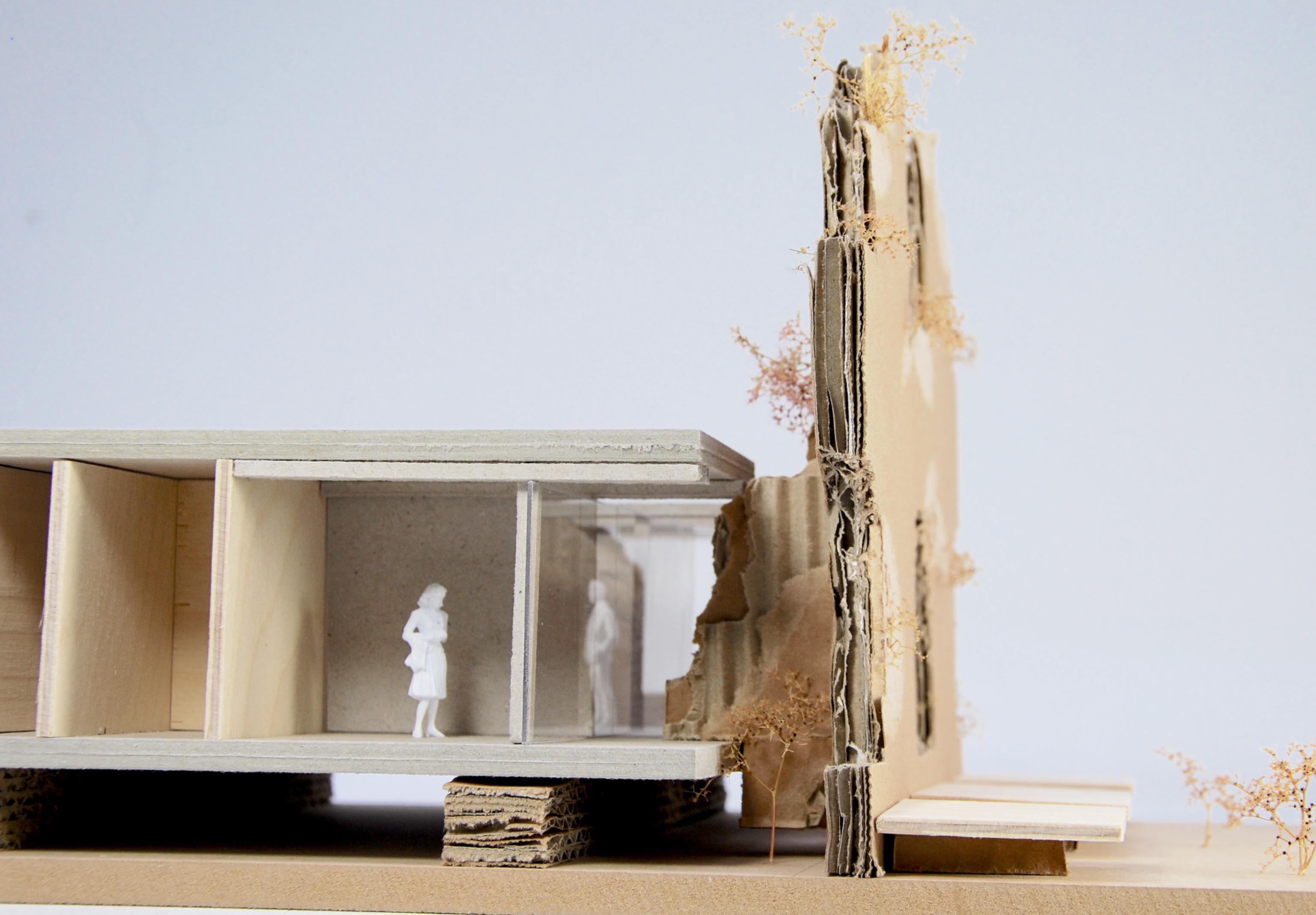
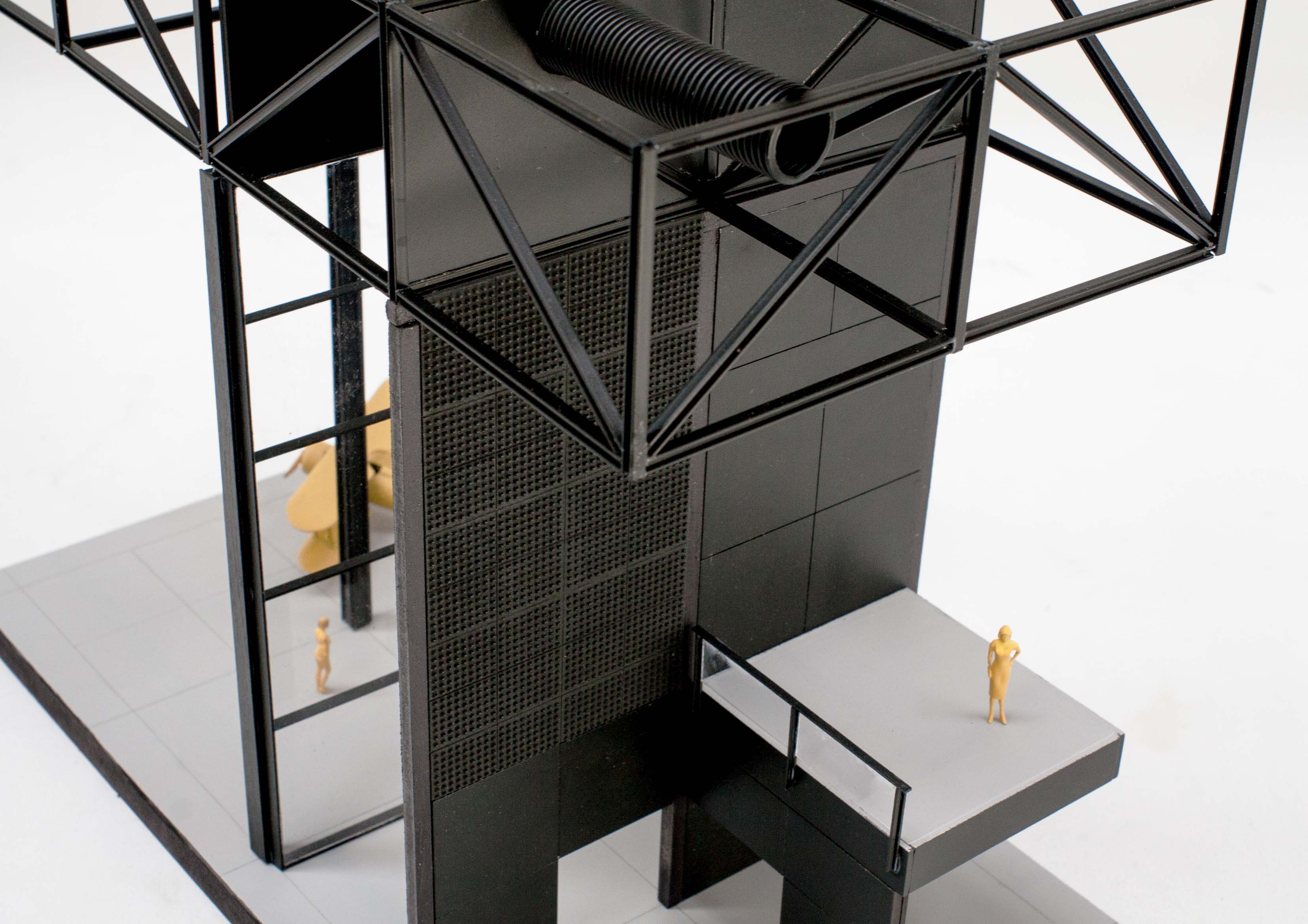
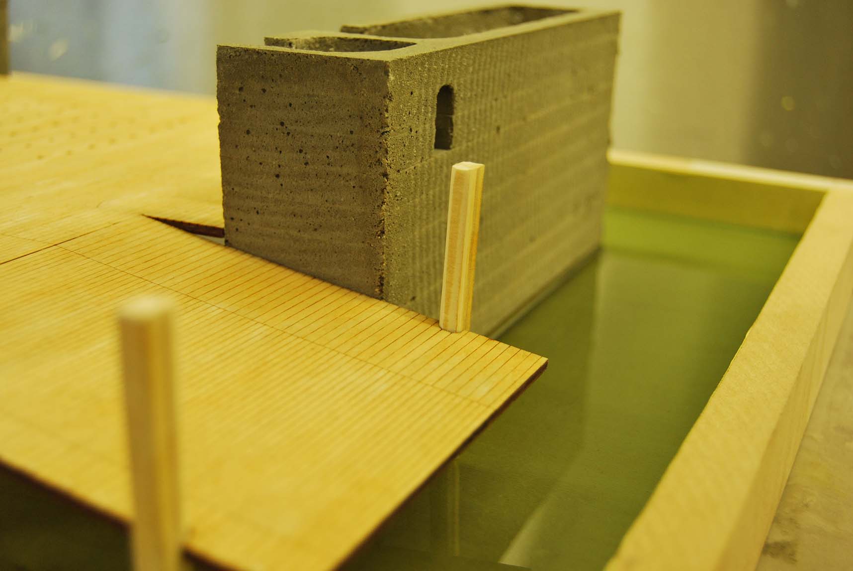
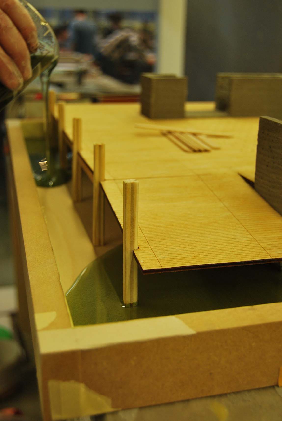
The base of the model was CNC milled out of a block of cross laminated pine wood, subsequently sanded and adjusted by hand in order for the 3d prints to fit. A total of six prints where needed to build the model, because of the limiting size of the printer. Gypsum can’t bear bending forces; therefor I introduced small wooden sticks inside the model to maintain stability. All the printed elements where modelled in rhino. The 3d printing program needs to have digital 3d models with closed edges; otherwise it is not able to print. With these organic shapes it can be hard to ban all ‘naked edges’. The wooden structure around the 3d printed part of the model cut by lasers. Due to the fact that it is such a small structure I chose to layer the beams with a Perspex frame on the inside; to gain strength and two layers of veneer on the outside; to maintain a certain aesthetic. For the tension cables is chosen for brass threat which is wired in-between the layers. It is inherent to every scale model to be an abstract representation of reality. Different levels of abstraction could be used depending on the specific story one wants to advocate through the architectural model. During the process it became clear that this model required a certain level of abstraction. Although the model is incomplete it contains an aesthetic value through its purity and functions as an expression of construction.

Het Platte Land-Colour and Tactility

The project proposes an alternative way to deal with the changing countryside of Groningen, the Netherlands. Instead of conserving the old, the proposal embraces new changes on the countryside to enrich the existing qualities of the landscape. The project consists of three equal big volumes, whose scale is put in relation to the big polder. In doing so the volumes can be experienced big and small simultaneously. By structuring all volumes introvert, the outer façade could be totally devoted to the surrounding landscape.

To summarize it was important to show the relation between the building and the polder landscape in my final model. Colour and tactility played an important role in this relation and I will therefore elaborate on both aspects. The model shown here is a 1:200 scale model with a size of 1400mm square.


Colour

To emphasize the relationship between the building and the landscape I decided to use realistic colours. To make a proper colour palette it is important to make multiple tests to see how the colour looks on the material and to see how all colours fit each other.

The red inner courtyard is made of concrete combined with red oxide pigment. Because it is hard to make small tests and copy the proportions exactly, I made a mould that could easily be reused. The mould was made of a laser cut in 0,4mm MDF with a layer of Vivak vacuumed on top. I sanded the Vivak to prevent the concrete of having a shiny surface. I used little nails to make holes for trees that were planted later.

For the process of pouring concrete its important to slowly add water to the cement and keep constantly mixing it. When the mixture is good (liquid, but not watery) you can add the pigment slowly and again keep mixing it. If you pour the concrete into the mould you can shake the mould (or softly tap it with a hammer) to fill the whole mold, equalize the surface and remove air bubbles. Do this again after 20 minutes or so.

In total I made three versions with three different colour tones. As advice I could say that you should not be too shy with the pigment and that the colour becomes lighter when the concrete dries.

Tactility

It was also important to show the difference between the rough landscape and the clean interior of the building. Therefore all elements of the building have been cut by a laser cutter, painted and assembled quite precise.

In contrast the landscape was mostly cut and assembled by hand. The base was of 9 mm MDF with corrugated cardboard to resemble the farmlands and a synthetic fibre mesh for the texture created by concrete tiles. I mixed the wall paint with potting soil and sand to roughen the surface. I used a round brush to dot (not stroke) to get a nice surface. Afterwards I sprayed the landscape elements with three different tones of green to create tone differences and an illusion of depth.

The facade was a bit tricky, because it had a curve in two directions and had multiple surface finishes. I decided to 3D print the base form of all four facades and from there treat the surfaces.

To fit the 3D printer, every facade element was printed in three loose parts. These three parts were glued together and the seams were finished with filler. Because 3D printers work in layers, the surface had a layered texture. To remove this texture, the elements were sanded multiple times and sprayed with Motip Spray-Putty. In this way slowly all ribs were filled and the surface became smooth.

However the upper part of the facade resembled reed and therefore needed a rougher surface than the lower part. Therefore I sprayed the upper part with spray-glue and afterwards lay it in a bed of fine sand. In this way you can easily add a thin layer of sand to a surface. So when the facade had the right tactility I could easily spray paint the whole facade element in the right color.

For me making this model was a nice way to experiment with different techniques, colours and textures to create various surfaces. By making quick and small tests (or take a look in the Cam-lab library) I could easily develop multiple variations. In doing so I could emphasize important aspects of my design.

Text, photos and model by Tiemen Anema

Nature and the Manmade

The following text has been written by Aiden Conway. Besides the description of the project, Aiden explains how to use acrylic one in an architectural model.

The project was aimed at discovering an approach to work in the isolated landscapes of Mayo in the West of Ireland. To do this the nature and the man made were put at odds to one another creating a conflict which would hopefully provide a method of resolving the two. This resulted in a series interventions that appear at first as a haphazard collection of volumes in the landscape, but are in fact a direct reaction to it. Each intervention creates a moment of detachment during which and an urban moment is constructed and the landscape denied, before the landscape is then reintroduced via the core function of the intervention. These forms were derived both from the study of the city and its formal components and as a reaction to the landscape in order to obscure it, reductions of both.

In any case when it came to modelling each one, the interventions was heavy and massive and wanted to contrast that by representing the landscape in a soft and light manner, as somewhat of a thin datum.

Each site and its greater context was illustrated accurately at a scale of 1:25000 in machine milled mahogany models. Because of this I thought the 1:100 models could be more expressive.

Form work_1   Curves   Final_1

Materials Required:

-Acrylic one Mix (consisting of the mineral powder and acrylic resin)
-Flexible Sheet of Fibre reinforcing
-3mm white Foam board
-30mm Foam board
 
The material Acrylic One was chosen to create this thin layer. It has visual properties similar to that of plaster but is much more durable and also workable after it has dried. The mould for each site was created via bending thing layers of foam and fixing them in the desired position. The openings into which the intervening volumes (cast in coloured concrete) were to be placed, were created by foam blocks. The entire formwork is then sprayed with an even coat of silicon spray to aid the casts removal from the formwork.

 The Acrylic one which is a two-component material and consists of a mineral powder and a water based acrylic resin was then mixed at a ratio of two parts powder one part resin and applied to the surface of the foam formwork. It sets quickly and so needs to be applied rather rapidly. Its best to create enough of a mix to coat the surface in one pour so as to limit the possibility of two pours where the wet and dry don’t always bond correctly and can lead to discolouration. I chose to apply the mix with a spoon so as to use the underside of the spoon to spread it across the formwork.

Once the initial layer is applied evenly and at a minimum thickness of 3/4mm and before its is fully dried the layer of fibre reinforcing is applied( pre-cut and trimmed to fit the formwork but also to remain at distance of 25-30mm form the desired edge of the form work so as to avoid loose and exposed threads). This should be flat to the surface and pushed gently into the still wet mix. After this the second mix should be applied. While it is preferable to pour the second mix while the first has yet to dry it is not completely necessary. The mix is then left to fully dry for at least 18 hours.

The foam formwork was removed. At some points had bonded with the acrylic was removed with the back of a knife or an upturned chisel, to scrape away the foam but also to take a thin layer of the surface with it if needed. once the form work was removed the remaining foam was sanded to the desired smooth finish. The cloth like undulations at the edges was created by cutting the curves on the wire foam cutter -passing it through vertically-  this was then glued to the formwork. The best results were achieved when the joints between the formwork and the curved blocks were as smooth as possible, but if not the workability of the acrylic one allows these joints to be smoothed out afterwards.

While I only had limited time to experiment with the material I think it has many potential applications and its limitations can be pushed much further than i had managed. I’d highly recommend it not only for its aesthetic values but also its workability after being poured, by which i mean the potential to alter its finish and also carve or work the surface.

Final_2

Foundry

The following text has been written by Max Nibbrig to explain his graduation project. Please click on the photos and take a good look. Max learned about the craft of bronze casting, but already knew about photography. And that’s an understatement.

Foundry pt.1

For my graduation project I designed a bronze foundry for the city of Amsterdam. The project aims at bringing back craft in to the city again by introducing a new place of work. Foundry pt.1 uses photography as a tool to explain architectural design. The images are pictures of 1:20 architectural scale models. These pictures explore spatial quality in relationship to light, atmosphere, material and use­. The photo series consist out of 11 pictures divided in to four themes; Foundry, Foundry Ceiling, Artist in Residence and Material and Detail. Moments within these four themes are carefully framed to show the potential of the space and the design.

The design consists out of two buildings. The big hall is a foundry for the casting of bronze and brass. On the central axis of the building the furnace is located where metals are melted. To the left and right there are casting pits where moulds can be placed to cast metal. Along the vertical axis of the building all the technical necessities as lighting, ventilation and movement are arranged.

The smaller space is an artist in residence building where artist can work in close cooperation with the foundry. He has his atelier on the ground floor and his living space on the first floor, making it possible to look down on the work whilst not working.

Both spaces deal with a floor that changes in to a plinth when the floor meets the wall. The plinth and floor work together to define a work area where things can be created.

1  2  3 4  5  6 7  8  9 10  11  12

 
Foundry pt.2

For my graduation project I designed a bronze foundry therefore I wanted to explore the possibilities of metal casting myself. Here fore I participated in a metal casting workshop organized by the Crafts Council in the Netherlands. In this workshop I had the possibility to create a metal casted site model of the location of my graduation.

I researched the possibilities of combining an old craft together with new production techniques. Sand casting is an old production technique for the casting of metals. This technique uses sand mixed with oil to create a mold. But before the casting can start the model needs to be created first. I made the site model first by 3d printing all the surroundings buildings and gluing them to a CNC-milled base plate. This model was then used to create the mold where the brass was casted in to.

In the accompanying pictures and movie you can see the process starting with the 3d printed objects to the finished model. The site model is in a 1:1000 scale and made out of solid brass. The four shinny bronze blocks is the final design of my graduation project. The ‘’legs’’ underneath the model are the air outlets of the mold. I decided to leave these on the model as a reference to the casting process.

1blog  2blog  3blog5blog  7blog  8blog9blog  Final_1blog  Final_3blog

Movies:

-Crafts Council video:
https://vimeo.com/132807849

-Sand casting a 1:000 architectural scale model in solid brass:
https://youtu.be/SIZ96zbk2D0

The City as Canvas, Architecture as Painting

The following text is how Tiwánee van der Horst describes her graduation project in relation to the modelling techniques she used to accommodate a time lapse movie.

2

The design for my graduation project was an organic structure where the shape was a result of a three dimensional translation of painterly movements and textures within a narrow alley. With my final model the aim was to show the designed building process through a time-lapse (see movie). For this it was needed to make a transparent surface onto which I could paint, so in the movie it would look like it was extruded in mid air.

 1    3    4

The options were either to 3D print the complex shape with a transparent filament or to deep draw with transparent Vivak. However the filament would never be entirely transparent. Therefore I decided to use transparent Vivak for deep drawing. For this it was necessary to make a mold through CNC milling. I divided the design into separate parts, which could then be laid out horizontally for deep drawing, after which all the parts could be glued together, creating the transparent paint surface.

6    7    8

The rhino file was prepared for the CNC milling process by the CAMlab. Because the deep drawing shows every single inaccuracy of the mold we let the CNC milling machine run multiple times until a smooth surface could be made out of the material. To prepare the mold for the deep drawing process it is necessary to create air holes through the block from the deepest points in the mold. To find these points I used a little ball from a bicycle wheel. After having found all the deepest points, the next step was to drill the holes through the block. The holes needed to be as small as possible other wise the holes would show in the surface of the Vivak. As the block was about 11 cm high it was not possible to drill through the block with the 1,5 mm drill. From the back I used a drill with a larger radius. However this process resulted to be to tedious and to risky. We needed to find another way.

19

With the help of the staff of the modeling hall we found a bicycle spoke with which we could drill small holes through the entire block height.


With all the air holes drilled and the corners smoothened it was time to give the deep drawing a try, but the block was too high and too large. 


10    11    12

13    14    15

To reduce the height by 14 mm we used a thicknessing machine and attached the block to a board with double-sided tape to insure the block to stay in place. Finally we succeeded to fully deep draw the block. Next up was the removal of the Vivak from the mold, by blowing air through the holes from the back.

16    17    18

I removed the surfaces that I needed for the model using a saw and utility knife. After attaching all the pieces together it was time to start the painting process. I set up the camera and lighting, prepared the color palette and started painting. The result of which is shown in the movie, giving a first impression of what a building process might look like when architecture becomes as painting.

TRA-DIGITAL HYBRIDS

The following text is how Nadia Remmerswaal describes the project.

During my graduation project I have focused on designing a safe housing solution for the Kampung of Indonesia. Making up 80% of the Indonesian cities, the Kampung are housing areas that are famous for their informal, self-build, organic growth that houses the low-to mid-low income city dwellers. It is paramount for these mega-cities like Bandung to be densified, but research shows that insufficient building knowledge is available in these Kampungs to construct higher than two storey buildings.
In my research I have focused on using new technology, like CNC milling, to design a durable, affordable,  customizable and above all safe building system that  enables the local community in these informal areas to build up to four storeys high.

research rapport

2. Uitsnijden gaten uit afplaktape  5. Ontkisten kolom  12. ResultaatNa en storten II  Storten beton  cOVERED_MG_1251  _MG_1231  _MG_1229

Nadia designed a re-useable moulding technique. To test and show the quality and esthetics she build a 1:7 scale mould and concrete scale model. In the building process laser cutting would be replaced by CNC-milling. The photo’s above show the process of the model: taping the MDF laser cut, building the mould, pouring concrete, covering the mould and the end result.

Wedges                    _MG_1242

The tile wedges made it possible to simulate wooden wedges on a smaller scale. A bonus is the impression of the seams in the mould visible in the surface of the concrete. Nadia has been nominated for the archiprix and she is competing for the ASN world prize.

A filament wound pillar


IMG_6505_2   Test A1   P1020529klein

Pierre Mostert’s graduation project focusses on the pillar for a pedestrian bridge. A glass fiber wire, pulled through resin, is wounded around a rotating mould. The weight test shows the small columns could hold about 1000 kg. Lots of hours of hard work and discussions and tests resulted in an impressive and realistic design.

P1040293_3

The Delta Shelter

The project shown here is exceptional in its process and outcome, because of the extensive use of scale models as a design tool and as a presentation tool. To show the process this post is the short version of the booklet Danique van Hulst made for the Argus Expo at BK City. 

The Delta Shelter is a six-week design project by the chair Form & Modelling studies during which the student has to develop a plan for a summerhouse on a Venetian island.
The project set-up has an exceptional design approach and method. During the design process the main design tool is the physical architectural model. The aim of the design course is to systematically integrate construction, design, materialization, detail and logistics. By making a vast amount of models each week, of different scales alongside each other, the plan is tested and developed on every level.

Making the First Sketch Models

After the introduction of the site and the assignment, some initial ideas are being translated into a series of small models. The models are more or less scaled 1:500. I made three series of three models. They all explore composition, position and some first thought about materialisation and technical solutions.

1    2    3 4    5    6 7    8    9

The first series of models explores the idea of a diagonal element within the composition. The second series of models explores a more crude implementation of a new building mass. The third series of models is based on an interest for a potential space between the old ruin wall and the
new wall of the house.

Exploration of Site & Composition

20

Exploration of the Passage

21

The line between interior & exterior

In the third week I continued exploring both the ensemble and the building layout using the 1:200 model. I focused on the placement of the façade in combination with the outlines of the roof and floor in order to explore the transition from the exterior into the interior.

29

31

Exploration of the Section

36


35

The line between interior & exterior

In the third week I continued exploring both theensemble and the building layout using the 1:200 model. I focused on the placement of the façade in combination with the outlines of the roof and floor in order to explore the transition from the exterior into the interior.

37
Testing model making techniques

As we are approaching the production time of the final presentation models, I have to make some decisions about the aesthetic, atmosphere and technique that fit the model that will represent my design. For the 1:200 model concerning the island ensemble, I made some test with cardboard and resin to represent both the landscape and waterscape. The reason I choose for torn cardboard to represent the landscape with its height differences is that the rough edges mimic the rocky shoreline. The choice for resin is based on its liquid appearance and pouring technique.

39     40

The second test I did is focusing on the 1:50 model where the focal point lays at the atmosphere of the space, which is highly influenced by materiality and light. The test concerns the cladding of an interior wall materialized from a darker warm wood.

45     47

Exploring the construction types

52

In this 1:50 model of a section of the summerhouse, I explored how the visibility of the construction can influence the atmosphere in the different zones in the house.

56    57    58

The final presentation

The location of the project consists of two small sinking islands in the Venetian Lagoon. The bigger island holds a 50m x 15m ruin from the 13th century that is decaying rapidly. I was fascinated by the slow disappearance of both the islands and the old structure. So I decided to let part of the island decay and hold on to the romantic notion of the ruin. At the same time I protected part of the island by implementing a water protection structure that also integrates logistics.

63    65    66

69

crop

71

72    73    74

75    76    77

Above the 1:50 model, below the 1:20 ‘impression of detailing’

79    80    81

82    83    84

Thank you, Danique!

Toolbox

Toolbox 1 Toolbox 1b Toolbox 2 Toolbox 2c Toolbox 3c Toolbox 4 Toolbox 4b Toolbox 4c Toolbox 4d
David Svahn, Hans Ahrland, Roman Oost and Roel Kosters each made a series of models for the Analytical Model course. The subject for this group was the NMM (Nationaal Militair Museum) in Soesterberg. This model is called ‘The Toolbox’ and can be seen as an assembly of building parts put together with the same proportions as in the original building. By remaking the models the message of the analysis comes across really clearly in the end. After every stage the group of students can discuss and refocus the analysis.

Resin pouring

DSC_8962small
Clara Jansen uses resin to show the water surface in her graduation model. A plate of plywood is used as a base because it’s stiffness and surface qualities. The edges have been sealed by pieces of MDF, which are treated to enable a smooth detachment. The resin has been colored by pigment powder to create the right contrast and to fit in the color scheme of the model.

DSC_8964small DSC_8966small DSC_8969small DSC_8972small DSC_8973small DSC_8974small DSC_8977small DSC_8978small DSC_8979small

Before pouring the volume of the resin has been determined. MEK harder is added to the resin in the right percentage and the resin mixture is being mixed by hand. This is only possible if the right safety regulations are regarded, don’t try this at home! The resin is being poured carefully and the model has to rest for a weekend.

IMG_1042s